Borg & Warner 4-Speed Manual Rebuild

Alexm

CCCUK Member
Yes! Had it all in, but now out again as more I played around with the old wiring started to doubt how long it would last?
So whole bulkhead back rewire now on the go.
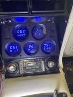
It’s a bit like some si-fi movies when I start it up, all dials start at zero then calibrate over about 15 seconds.
 

Attachments

  • IMG_4846.jpeg
    IMG_4846.jpeg
    295.1 KB · Views: 5

Forrest Gump

CCCUK regional rep
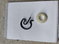
Looking at your photo, your clips don’t go in as far as mine. The hook shaped bit sits against the straight bit, if that makes sense.
I think the shape of these clips as supplied is a bit suspect tbh - as per pic below.
With just a little bending I have improved the shape of the spare clip so that the legs touch as you say and also squashed it down a bit so that it hooks further under the rod….if that makes sense!
C8ED1BAC-619B-4465-85A5-C52594F47197.jpeg
 

Forrest Gump

CCCUK regional rep
Four Gallons ?

Is that with mixing 50/50% with water ?

I used a little less than four of those 4 litre cans.
4 litres is just slightly more than a US gallon (but is less than our imperial gallon). The cans are pre-mixed so that was the total capacity.
I’m not running a heater core or pipe work which reduces my capacity by an amount.
 

Roscobbc

Moderator
I already have poly engine mounts fitted. They’re so solid I can’t imagine they give much cushioning from vibration!

View attachment 24276
The poly engine mounts may look unyielding but should improve the shifting quality even of manual transmission cars with stock body mounted shifters by reducing engine movement due to torque when accelerating and decelerating. This movement, in turn can translate to sideways movement of the shifter when 'hitting' the gas pedal and often made worst if the OEM shifter has seen better days.
Some of the 'Septics over the pond with higher powered car actually use solid mounts........not so sure that is a good thing. Stock C3 engine mounts have an interlock device which prevents the engine rising-up fully if the rubber bonding of the mount fails..........it's supposed to stop things like the air filter hitting-up against the underside of the hood and fan blades 'eating' away the fan shround. Indications of a mount failing (usually the driver side) is a of degree juddering/scuttle shake when upshifting gears. This may initially perhaps appear to be clutch or chassis issue.
 

teamzr1

Supporting vendor
How design of motor mounts have changed over time

Here is that base C8 Stingray motor mount
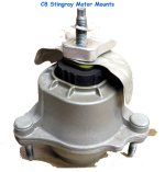
s-l1600.jpg

But do to the flat plane crank LT6 of Z06, Electrically controlled
Magneto-Rheological (MR) Powertrain Mounts are used in the automotive powertrain environment and are designed to isolate vibrations from the vehicle’s body while also providing exceptional powertrain motion control.

Unlike conventional hydraulic mounts which provide peak damping at a single frequency and amplitude, the Magneto-Rheological (MR) Powertrain Mounts can provide high damping over a broad frequency and amplitude range.

Using magneto-rheological (MR) fluid to change the damping rate in real time, these powertrain mounts may be “firmed up” with high levels of lateral acceleration for more direct cornering, or “softened” for maximum comfort during straight-ahead driving.

Furthermore, the combination of effective control of powertrain motion with good attenuation of noise and vibration simultaneously improves vehicle stability and interior refinement.

The original Magneto-Rheological (MR) Powertrain Mounts were engineered for performance and configured for premium sports car applications. They prevented large transient powertrain movements (in the frequency range of 2-22 hz) from reaching the chassis.

The second generation design retains this capability while also providing isolation from smaller amplitude movements in the critical comfort range of 30-150 hz, enabling the technology to be applied to touring vehicles where superior levels of refinement are required.
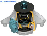
C8Z06motormount-.jpg
 

Forrest Gump

CCCUK regional rep
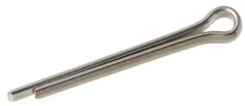
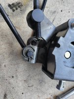
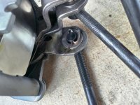
After last weeks Clevis pin failure just ten minutes into the test run, I don’t have much confidence in these particular items that were supplied in the [not inexpensive] Hurst installation kit. There are six of them in total on the shifter set-up. I’m going to replace them with split pins - they won’t come out.
To change them all means taking the whole shifter assembly out of the car again, taking it out from underneath the car - a real pita job just to change a few pins!! There is just no access to pins at the lever end of the rods because of the chassis cross member.

Pic below shows the one of the “suspect” clevis pins and on the arm below I’ve already replaced with a split pin and thin washer.
7ED01DE2-8649-402C-A8C7-8761C0EA7BFB.jpeg
40274A14-2764-4CB5-BFC0-97BEBA547B86.jpeg

I’ll take the car out for another test run tomorrow. Then it’s the North Weald driving day on Thursday so that will put the gearbox and shifter through its paces!
 
Top