Fuel system

UKenGB

New user
Much as I really like the C7 Corvette, I am looking into installing a C7 drivetrain into a different car and hoped I might obtain answers here to a question about the fuel system.

I know the C7 has twin tanks and how they work and also that the LT1 has a mechanical high pressure pump. What I am trying to establish is the stuff in between.

First of all, is there a feed and return between tank to engine?
Is there a pressure regulator to hold a certain pressure in the feed line from which the HP pump will draw fuel?
What other parts are involved in the fuel system? Not the individual lines and hoses, but the functional parts.

Most could be worked out from first principles, but would help enormously to know how GM have set this up and I'm having great difficulty finding out. So hope someone here could help.
 

teamzr1

Supporting vendor
Read this post I wrote last year


Make sure the seals between the transfer tube are new and installed correctly as at least with the C7s
Any detailed work on this requires the whole ass end taken out to get to these
Also needed is the fuel system controller
Return fuel lines are not allowed as to US EPA, so there is only one fuel line from tank to engines fuel rail
Thus, regulator is in the back

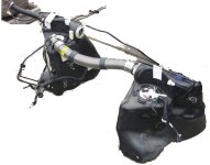
c6tanks.jpg

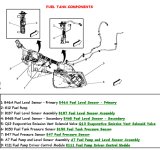
Ctfueltankparts.jpg
 

UKenGB

New user
Yes I did read your post thanks, but that only concerns how the twin tanks function together and as I will just have a single tank, none of that will be necessary.

I remain puzzled though as you say a return from engine to tank is not allowed in the US, so pressure regulator is at the back and only a single fuel line to the engine. That makes sense, but both images above clearly show 2 fuel lines running forward from the rear assembly and I can only assume those go to the engine, which looks like a traditional feed and return setup.

A Fuel Pressure Sensor is shown in the diagram but is that actually a pressure regulator or just a sensor that the Control Module uses to electronically regulate the fuel pump output? In which case, why the 2 lines forward to/from the engine?
 

teamzr1

Supporting vendor
I believe there is one fuel line from the left tank to engine, that is the low pressure (60 PSI & lower) fuel to left side of fuel rail
Another fuel line from tanks is the fuel feed for the high pressure pump on engine which than goes to the right fuel rail
as need for the direct injection pressure
But no return fuel line and if I recall the fuel regulator is inside the left tank
Not sure without thinking about this but if your only using one tank how you work with the electronics as to the fuel gauge
logic of the float senders in each tank
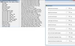
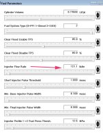
Clearly might handle with some changes within the PCMs calibration as I show several fuel system tuning tables
and maybe turning off fuel sender DTCs via tune

C7fuelpcm.jpg
 

UKenGB

New user
I believe there is one fuel line from the left tank to engine, that is the low pressure (60 PSI & lower) fuel to left side of fuel rail
Another fuel line from tanks is the fuel feed for the high pressure pump on engine which than goes to the right fuel rail
as need for the direct injection pressure
But no return fuel line and if I recall the fuel regulator is inside the left tank
Not sure without thinking about this but if your only using one tank how you work with the electronics as to the fuel gauge
logic of the float senders in each tank

Further research has revealed that a single fuel line feeds the HP pump, the output of which is then split to both L and R fuel rails and as you say, no return. The HP pump requires 75 psi and is fed from the in-tank pump. There is no regulator, just the sensor and as I was in fact wondering, the LP pump is controlled by PWM in order to maintain the constant 75 psi to the HP pump.

So why the second line to the engine?

Ah, I think it is in fact split from the LP side to feed back to the RH tank and is used to 'pump' fuel from R to L tank. I thought that split would be back by the tanks, but looks as if it is actually done further forward.

Now it all makes sense.

My project is not a Corvette and has a single tank. I just need a PWM controllable pump in that tank and a single fuel line forward to the engine, connecting to the HP pump input. The output from the tank needs the pressure sensor (probably have to make an adapter), then the Corvette pump ECU should be usable to control the LP in-tank pump and maintain constant pressure to the HP pump input.

I think I've got it now. Thanks for your input.
 

teamzr1

Supporting vendor
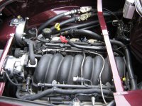
Over many years, I have worked with vehicle owners that were doing LSx power and drivetrains on all types of
restores or designing their own vehicle where I did the custom tuning to make it all work correctly

No matter what type of other nameplates they own, the LSx is the path they go to

Here is a real odd ball
2 retired guys spent years on taking their C6 with their design of a EV


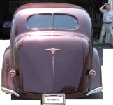
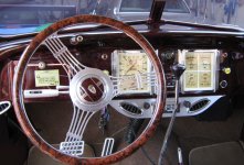
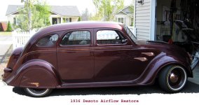
One of the nicest restores I worked on is this 1936 Desoto Airflow

1441.jpg1445.jpg1443.jpg1440.jpg
 
Top