BB Fan conversion, Back to basics!

Knodty

Well-known user
Hi Guys some of you will know I’ve been running Twin Spals on my Vette for some years now. I fitted them after having a catastrophic flex fan failure.
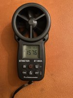
I recently acquired a BB fan shroud and will be looking to fit it over the Christmas holiday. I know the Spals do not move as much air as the stock fan and have in the past tried to get information regarding this. However I went out on a limb and bought an Anemometer and set it to CFM and got a reading of: 1576 CFM. Not sure how accurate it is but I will be able to get comparable readings between the two. I had a similar reading for both electric fans. I will update you with the readings when I fit the stock fan and Shroud on the car. Not sure if I have to calculate anything as to the size of the Fan diameter and distance from the blades, however is gives me a starting point.
 

Attachments

  • IMG_2229.jpeg
    IMG_2229.jpeg
    256 KB · Views: 2

Forrest Gump

CCCUK regional rep
Hi Pete,
Interesting experiment you’re doing. I guess a big variable between electric and mechanical fan is the mechanical fans CFM is governed by engine speed. So when you’re stuck in traffic and engine is getting hot, the mech fan is also at its slowest rate at idle speed. I think the owners manual actually says you should raise the revs to help it out! Same applies to the water pump output. Elec fans can be switched to full whack as required of course.
Temperature sensors at inlet and outlet of radiator would be another good monitor of each fans cooling rate. You’re the plumber!!
 

Roscobbc

Moderator
In theory the mechanical fan should 'windmill' (courtesy of the viscous coupling) if the engine temperature hasn't exceeded the design temperature of the viscous coupling installed (and they do differ according to OEM engine spec').
Once engine block temperature exceeds the design temp the viscous unit should activate, 'lock-up' and bringing the fan into play irrespective of whether engine is at idle speed or cruise. Coupling is a 'soft' function and slips a litle so usually runs a little slower than engine rpm. They come in 'standard duty', 'heavy duty' and 'extreme duty' options, the latter being generally for trucks.
 

Knodty

Well-known user
Hi Andy/Ross, I must admit I never before I fitted the electric fans had a problem with overheating in traffic even on very hot days, Only had that problem with the Spals. I did have a 7 blade stock fan fitted originally (as it did have Air Con) and I do wonder what the difference between the 7 & 5 blade regarding air movement would be. I only have a 5 blade to try now as I sold my 7 blade years ago, but would like to try it with both TBH. I’m looking forward to the results and just see what the difference is.
One thing I did notice was that once the Spals switched on via the thermostat they stayed on for the duration of the journey, they never cooled the engine down enough to switch off. The only time they ever shut off was on a motorway journey in 10 deg C air temp.
 

Knodty

Well-known user
Hi Pete,
Interesting experiment you’re doing. I guess a big variable between electric and mechanical fan is the mechanical fans CFM is governed by engine speed. So when you’re stuck in traffic and engine is getting hot, the mech fan is also at its slowest rate at idle speed. I think the owners manual actually says you should raise the revs to help it out! Same applies to the water pump output. Elec fans can be switched to full whack as required of course.
Temperature sensors at inlet and outlet of radiator would be another good monitor of each fans cooling rate. You’re the plumber!!
Trouble I found on mine was that all the thermal switches failed within a year which was why I ended up having to fit a manual switch instead. Being a black car i think it magnifies the heat in the engine bay. 😖☹️
 

Knodty

Well-known user
Have you considered swapping with a colder coolant Tsat and a higher volume radiator ?
Already fitted a 160C stat, years ago as I didn’t want the thermostat starting to shut off the waterflow before the control stat for the fans switched on at 180c. Never changed the rad as I cooled the car before with the stock Fan, all be it with more Airflow.
 
Last edited:

Forrest Gump

CCCUK regional rep
I wonder if the shroud set-up with your spall fans was restricting the airflow through the rad when the car was moving? You’d think the fans would turn off soon after the car is moving. The stock shroud is very “open” whereas electric fan setups tend to have a close fitting shroud just an inch or so away from the back of the rad. It’s a bit of a trade-off trying to get the fans to draw air across the whole rad, but must affect the airflow through the rad when the car is moving. Electric fans themselves clutter the airflow too.

A single electric fan with no shroud works well on my SBC car but I know BBC’s do challenge the C3s cooling system limitations.

I’ll have a look for my old stock fan. It was an a/c car originally so might be seven blades, you can try it if it’ll fit.
 

Knodty

Well-known user
I wonder if the shroud set-up with your spall fans was restricting the airflow through the rad when the car was moving? You’d think the fans would turn off soon after the car is moving. The stock shroud is very “open” whereas electric fan setups tend to have a close fitting shroud just an inch or so away from the back of the rad. It’s a bit of a trade-off trying to get the fans to draw air across the whole rad, but must affect the airflow through the rad when the car is moving. Electric fans themselves clutter the airflow too.

A single electric fan with no shroud works well on my SBC car but I know BBC’s do challenge the C3s cooling system limitations.

I’ll have a look for my old stock fan. It was an a/c car originally so might be seven blades, you can try it if it’ll fit.
Yeah I think you are right as there is a lot of restriction to surface area covered by the fans also. I worked out last night that the area of the Spals is 190 sq in however the stock fan is 254 sq in. The negative thing with the electric fans is that the shroud only covers I’d say 80% of the Rad surface so in traffic there is no airflow across 20% of the Rad which will add to water temps.
I got to the stage where I’d had enough of the problems associated with the electrics on the fans. I’d fitted a couple of 40 amp circuit breakers to the fans as the heat was melting the rubber casing around the fuses and had melted one of the fuses. 😳😖 The circuit breakers started to fail within 1 year of little to no use. Very frustrating to say the least. Sorry forgot about the Relays failing as well.
 

teamzr1

Supporting vendor
Going back to 1980s and I would test electronics in design such as desktop computers and using a thermal chamber I found
for the fan to do its best, there needs to be pressure and increasing velocity
Add the angle of the fan blades and in this case the shroud to help do the above

In short engineering choice what the design of the cooling fan would be
With the cover off the computer with the cooling fan working, the components would get hotter but when the cover was installed created pressure,
the airflow from fan speeded the airflow and the added pressure of the correct size of the outlet of the case and thermal airflow increased, reducing the temp in the case

Think this write-up helps explain that

Under Pressure - The Basic Principles of Air Movement

This article explains the basic principle of air movement; how creating a pressure differential is the key to creating a flow of air; and how we can measure pressure – the first step in selecting the right fan to provide the desired air flow.

Why Air Flows


In one respect, air is like water, it will naturally flow from an area of high pressure to an area of low pressure.
A domestic water system is generally under pressure (usually around 30psi), so when you open a tap, the pressure at that tap falls to zero, which causes water to flow to the low-pressure area.

Air is a fluid, just like water. It will also flow from one area to another because of a difference in pressure. Therefore, to create an airflow, we need to create a pressure differential. A fan causes air movement (or ‘flow’) by creating that pressure differential, causing air to move from the area of high pressure to the area of low pressure.

The amount of air which will flow through a duct, and the speed at which it will flow, are both dependent on the degree of pressure difference which is generated (and by system resistance, or friction). The higher the difference in pressure, the greater quantity of air will flow in a given period of time.

For an Axial flow fan, this increase in pressure differential is created by changing the impeller “pitch angle”.
The principle therefore is that a higher impeller blade angle will create a greater pressure differential and an associated increase in air flow. It should also be noted that increasing the impeller blade pitch angle will also increase the amount of power needed to drive the impeller.

Defining Pressure

There are several different terms used in measuring and defining pressure. As they are all inter-related, it is important to be familiar with each term, as well as the units used to measure them.

There are four main factors we need to consider:
  • Air Velocity: this is simply the speed of air in a given direction, past a fixed point. It is measured in meters per second (m/s), and is given the symbol ‘v’.
  • Volume Flow Rate: this is the amount of air passing a given point in a given unit of time. It is measured in cubic meters per second (m3/s), and is given the symbol ‘qv’. It can also be expressed as the average air velocity multiplied by the area of the measuring plane.
  • Static Pressure: this is the pressure which acts equally in all directions, and is the pressure which maintains air movement against a resistance. It is measured in Pascals or Newtons per square meter (Pa or N/m2), and is given the symbol ps, or when a fan is involved, psF.
  • Dynamic (or Velocity) Pressure: this is the pressure which is due solely to the speed of the air movement, and it acts in the direction of the air. It is also measured in Pascals (Pa or N/m2), and is given the symbol pd, or when a fan is involved, pdF.
  • Dynamic pressure can be expressed by the formula pdF = 0.5 ρ v2 (where ρ is air density in kg/m3 and v air velocity in m/s).
How They Are Related

From these factors, we can calculate the total amount of energy in the air at a given point, which is known as Total Pressure. Total Pressure is the sum of the Dynamic and Static Pressures (not to be confused with the total sum of the static pressure drops within a ductwork system). Total Pressure is measured in Pascals (Pa or N/m2), and is given the symbol p, or when a fan is involved, pF.

Given that Total Pressure is the sum of Static Pressure and Dynamic Pressure, we can deduce some simple formulae to help understand the relationships between each type of pressure:
  • Total = Static + Dynamic, or pF = psF + pdF
  • Dynamic = Total – Static, or pdF = pF – psF (where pdF = 0.5 ρ v2)
  • Static = Total – Dynamic, or psF = pF - pdF
Measuring Pressure

The most common tool used to measure pressure both on site and in a standardized laboratory condition is a Pitot Tube (also known as a Pitot Probe). Invented by the French engineer Henri Pitot in the early 18th century, it was developed into the form we still use today in the 19th century by Pitot’s compatriot Henry Darcy.

As well as being used to measure liquid, air and gas flows, the Pitot Tube is also widely used to determine the airspeed of aircraft, and the water speed of boats.

A typical Pitot Tube is designed to give us the opportunity to measure the directional component and therefore the Dynamic Pressure (which, as we have seen, acts in the direction of the air).
This is important, because it then becomes possible to derive a value for the Total Pressure, by adding the Static Pressure to the Dynamic Pressure, using the above formula.

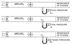
The three types of pressure are measured in slightly differing ways. To measure Static Pressure, a perpendicular tube exits the duct.
The tube contains fluid, which is brought to rest (stagnates) as there is no outlet to allow the flow to continue.

Total Pressure is measured in the same way, except that the entry to the tube points directly into the air flow.
To measure Dynamic Pressure, the entry to the tube again points into the air flow, but the tube itself has a perpendicular outlet back into the duct.
basic-blog-2.jpg

An alternative method is to use the ‘side tapping’ method, which relies on ‘tapping points’ on the side of the casing or duct. However, this only allows the measurement of Static Pressure. In order to measure Dynamic Pressure (and hence determine Total Pressure), it is first necessary to measure the velocity of the air moving through the fan.

A disadvantage of using a single side pressure tapping method (in a test duct) is that it can be affected by uneven pressure profiles within the system. To minimize this, it is usual for laboratory test ductwork to have multiple ‘side pressure tapping’ positions around the duct, so that an average pressure value can be obtained.
 

Knodty

Well-known user
Team ZR1 interesting article. I think as you said the temps increased when the casing was open, is down to the fact you open up the complete area to atmospheric pressure which doesn’t allow for the pressure drop and limits the natural flow of air caused by the pressure drop.
 

GiuG

CCCUK Member
In theory the mechanical fan should 'windmill' (courtesy of the viscous coupling) if the engine temperature hasn't exceeded the design temperature of the viscous coupling installed (and they do differ according to OEM engine spec').
Once engine block temperature exceeds the design temp the viscous unit should activate, 'lock-up' and bringing the fan into play irrespective of whether engine is at idle speed or cruise. Coupling is a 'soft' function and slips a litle so usually runs a little slower than engine rpm. They come in 'standard duty', 'heavy duty' and 'extreme duty' options, the latter being generally for trucks.
Interesting! Is the fan clutch drive the fan, which clutch I need to have, in order to allow the fan engage quicker if temperature rise? Is the "heavy duty" and the "extreme duty" refer to the size of the fan weight you can mount ( some are pretty heavy ) or rather to the Volume of air they can move in CFM?
My point is, if I want to swap a 5 blade to 7 and enlarge a bit the diameter, I need to change the fan clutch as well?
 

Roscobbc

Moderator
Interesting! Is the fan clutch drive the fan, which clutch I need to have, in order to allow the fan engage quicker if temperature rise? Is the "heavy duty" and the "extreme duty" refer to the size of the fan weight you can mount ( some are pretty heavy ) or rather to the Volume of air they can move in CFM?
My point is, if I want to swap a 5 blade to 7 and enlarge a bit the diameter, I need to change the fan clutch as well?
Doubt if you would be able to source larger diameter 'fan' blades - just the 7 bladed fan - even if you could a new shroud would be needed. TBH the GM engine cooling fan technology is not very well explained, either by GM day 'in the day', more recently by knowledgeable 'experts'.
The American way was (and still is) to replace the OEM unit with an aftermarket electric fan assembly, either new or off a late model car.......but with zero information from GM relating to stock fan performance are the aftermarket fan units an improvement? - perhaps not.
It's generally accepted that the early C3's (mine is a first year car) had inadequate cooling, particularly when the big block and more powerful engine options were installed. Later cars had revised nose cones and air dams to direct more cooling air in to the radiator.
Mine is (was) a L36 390 hp manual, no ac car. It was always 'marginal' in cooling terms on hot days. Radiator was past its best. Water pump had badly OEM eroded steel impellor (probably from years of insufficient antifreeze in system) - bottom of radiator and engine block were full of crap. Some of the rubber seals around the radiator and shroud had deteriorated. When I replaced the engine with its current 570 hp 489 cu in engine the existing radiator fell apart.
I bought a new DeWitt OEM style alluminium radiator and attended to making sure that ALL the cooling air coming through the nose cone ONLY went through the radiator and 'sealed' any gaps up between the shroud and the radiator.
10 years later.......now - and the car runs cool enough on mild summer days (perhaps too cool on colder summer evenings) and stays between 185 F and 190 F on on a 60 mph cruise on a 30 C degree day.........but temperatures will start to climb towards 200 F when driving continuously over 80 mph or caught in stationary traffic.
It seems that careful selection of a thermostat helps to optimise cooling and an efficient, perhaps high volume water pump is vital - I am currently using an adjustable thermostat (a Nissan item....don't ask!)
Look on Rock Auto's website - it shows various viscous fan options for specific year Vettes - including standard, heavy and extreme duty units......however not all opf them are available.......and they do fail - mine went a couple of year ago.......clue's? - visible 'oil' around the centre of the viscous unit.
 

teamzr1

Supporting vendor
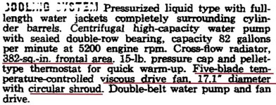
If looking at the GM PDF I attached in the above post, you see that each of the 4 engines has a different cooling system

Here is the L72 cooling system design

cool66.jpg
 

GiuG

CCCUK Member
Doubt if you would be able to source larger diameter 'fan' blades - just the 7 bladed fan - even if you could a new shroud would be needed. TBH the GM engine cooling fan technology is not very well explained, either by GM day 'in the day', more recently by knowledgeable 'experts'.
The American way was (and still is) to replace the OEM unit with an aftermarket electric fan assembly, either new or off a late model car.......but with zero information from GM relating to stock fan performance are the aftermarket fan units an improvement? - perhaps not.
It's generally accepted that the early C3's (mine is a first year car) had inadequate cooling, particularly when the big block and more powerful engine options were installed. Later cars had revised nose cones and air dams to direct more cooling air in to the radiator.
Mine is (was) a L36 390 hp manual, no ac car. It was always 'marginal' in cooling terms on hot days. Radiator was past its best. Water pump had badly OEM eroded steel impellor (probably from years of insufficient antifreeze in system) - bottom of radiator and engine block were full of crap. Some of the rubber seals around the radiator and shroud had deteriorated. When I replaced the engine with its current 570 hp 489 cu in engine the existing radiator fell apart.
I bought a new DeWitt OEM style alluminium radiator and attended to making sure that ALL the cooling air coming through the nose cone ONLY went through the radiator and 'sealed' any gaps up between the shroud and the radiator.
10 years later.......now - and the car runs cool enough on mild summer days (perhaps too cool on colder summer evenings) and stays between 185 F and 190 F on on a 60 mph cruise on a 30 C degree day.........but temperatures will start to climb towards 200 F when driving continuously over 80 mph or caught in stationary traffic.
It seems that careful selection of a thermostat helps to optimise cooling and an efficient, perhaps high volume water pump is vital - I am currently using an adjustable thermostat (a Nissan item....don't ask!)
Look on Rock Auto's website - it shows various viscous fan options for specific year Vettes - including standard, heavy and extreme duty units......however not all opf them are available.......and they do fail - mine went a couple of year ago.......clue's? - visible 'oil' around the centre of the viscous unit.
Man you`re always super precise, thanks. But what in this case heavy duty means... and also I find instead the stock 17" fan the 18" and 19" replacement instead. At the moment I don`t have the shroud so for me is easy to swap, but I don`t know if is woth to try
 

Roscobbc

Moderator
Man you`re always super precise, thanks. But what in this case heavy duty means... and also I find instead the stock 17" fan the 18" and 19" replacement instead. At the moment I don`t have the shroud so for me is easy to swap, but I don`t know if is woth to try
Shrouds can be expensive to source - remind me what year/engine option is yours? - I would 'read' Standard Duty as LoPo small blocks, Heavy Duty as relating to HiPo small block, big block and perhaps all engines with a/c - Extreme Duty for trucks, RV's etc......perhaps Jon knows more?
 

teamzr1

Supporting vendor
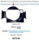
For 1965 and 66 shrouds listed for 327, 396 and 427 CI
Maybe what difference in called small block, heavy and HiPro ?

Damn costly for repos in fiberglass and taking up to 60 days to ship

repo427.jpg
 

GiuG

CCCUK Member
Shrouds can be expensive to source - remind me what year/engine option is yours? - I would 'read' Standard Duty as LoPo small blocks, Heavy Duty as relating to HiPo small block, big block and perhaps all engines with a/c - Extreme Duty for trucks, RV's etc......perhaps Jon knows more?
Mine is 1975 SB, so in this case I suppose is "standard" clutch, cause I don`t have a lots HorsePower to my arsenal and yet during the summer the engine lock down, and revive the next day after a cooling night. So to make the story short, the Fan clutch type is related to the horse power, rather than the size of the fan right?!
 

teamzr1

Supporting vendor
Yes when the fan clutch is engaged it puts more of a load on the crank via the pulley belt, so does this at the cost of performance
Newer GM vehicles designed with electric cooling fans to remove that drag and even never models also have electric power steering
to also remove that drag/load off the crank
 
Top