Project black hole sun.

Dorsetsteve

Well-known user
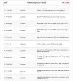
Thanks that’s very helpful. I seems I can check them.
They are listed as exampled, in the photo.IMG_1345.jpeg
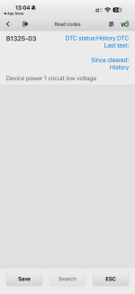
Then I can also look at them differently.
IMG_1344.png
 

teamzr1

Supporting vendor
If you had cleared DTCs and all these DTCs already tripped you need to start debugging them
DTCs starting with P are Powertrain (PCM), B would be Body/chassis (BCM)
But if the scanner is valid reporting you have multi engine issues

Go to this website and enter each DTC, and it will tell you more information what is wrong and maybe how to fix


As I mentioned in other post you need to start scanning and recording fuel trims, front O2s, etc to see the health of how engine is functioning
I'd check fuses like 5 volts reference, O2 heater, MAF, MAP and TPS

With scanner select PIDs (Parameters) for below to be able to scan and/or record them


  1. With coolant temps around 180F degrees at idle
  2. Engine should be in Closed Loop
  3. Bank1 (B1) is left head, B2 Bank2
  4. Front O2s would be Sx, so HO2B1S1 would be left O2 before CAT
  5. LTFTs around +/-5% average
  6. Front O2s around 0.500 mVolts
  7. MAP about 35 Kpa (if close to sealevel)
  8. ECT coolant, about 190ish F degrees

If PCM is not going to "Closed Loop" than PCM is not seeing the sensors that tripped those DTCs reporting normal
 

Dorsetsteve

Well-known user
I have cleared them but I haven’t driven the car and come back. I just popped to the garage quickly to hook it up and see what’s what. I’ve pulled the data and will once I’ve driven it again, pull it once more and compare.
 

teamzr1

Supporting vendor
The scanner should have a "Reports" function and also "Freeze Frame"
scanner should build those and allow you to either read, print or email to you and
all that information you see be in those
 

Dorsetsteve

Well-known user
I pulled them as a PDF so I can compare the whole file.
I’ve had an issue with reverse from the beginning. And this is on the list. Hopefully that will assist that issue.
P0801-00 Last test: Reverse inhibit solenoid control circuit
 

teamzr1

Supporting vendor
Reverse Inhibit Description and Operation
The reverse inhibit solenoid is a safety feature which prevents an inadvertent shift into reverse at speeds above 5 km/h (3 mph). The system consist of the following components:
^ The powertrain control module (PCM).
^ The reverse inhibit solenoid.

With the ignition ON, battery voltage is supplied directly to the reverse inhibit solenoid.
At forward speeds above 5 km/h (3 mph) the PCM opens the control circuit of the reverse inhibit solenoid.
This de-energizes the solenoid and mechanically blocks the shift lever from going into the REVERSE position.

Solenoid has 2 wires, one is 12 volts and other is command wire from the PCM

 
Top