What have YOU being doing or are you planning to do with your Vette?

CaptainK

CCCUK Member
I am watching , and shame on you ! You shouldn`t be going off on jollies .
I did a tiny bit more to my loft yesterday. I'm planning out bridges and raised sections and stuff. All very basic stuff to do proof of concepts etc. Still toying with ideas.

In car related news:
1) I tried to take the rear bumpers off my 1968. It turns out the bolts accessed from the outside of the car are dead easy to undo. The ones in the corners of the car are rusted like mad and I can't get good access to them. I tried for a bit and got them going a little bit out, then heard a loud bang and decided I'll give up - after all the Vette was booked into the garage today for its "yearly check". So they can do it for me. I'm taking the bumpers off as they are a bit skanky now, and figured they needed to be shiny.
2) I jacked up my project car with the aim of changing oil and filter. Sump plug I could undo, but oil filter in an awkward place so I'm gonna have to have a think on that and maybe buy a fancy oil filter removal tool.
 

antijam

CCCUK Member
Anyone who's worked on a roadworthy but unrestored fifty year old car will know that it's a gift that keeps on giving. Having had to repair and refurbish the passenger side header on my '71 as a knock-on effect of dealing with a starter motor problem, I now have a smart black header on one side but a tattily wrapped rusty one on the other.

P1370297.JPG

Time to go for a matching pair. Removal of the driver's side header is a little trickier than the passengers. The alternator and its mounting bracket have to come off (the bracket is secured with the front two manifold bolts) and on a manual the clutch cross shaft ('Z' bar) must be removed. With the car jacked up and on an axle stand I squirm underneath, grab hold of the cross shaft to help pull me into position - and it literally comes away in my hand!

The shaft is supported on two ball ended studs, one screwed into the engine block and the other attached to a bracket on the frame. Having pushed the shaft onto the block stud, the other stud is fitted into the other end of the shaft and it's threaded end drops into a slot in the bracket where it's secured with a tab washer and nut, the tab washer having a tang that engages a slot in the bracket to prevent the cross shaft lifting out.

clutch shaft assy.jpg

Turns out I don't need any spanner work to remove it. The securing nut (arrowed pink) is not even finger tight and it's tab washer (arrowed green) missing; at the other end, the stud (arrowed red) is loose in the block.

One of the things in it's favour when I bought the car was that it had just had a new clutch fitted. What I didn't know was that the work had been done by Bubba's UK cousin. As well as the loose fittings, the grease seals (arrowed blue) at both ends were missing and Bubba presumably not having a new tab washer to hand, had decided to fabricate his own.

P1370315.JPG
Correct tab washer left - Bubba's replacement right.

He obviously had no concept of its purpose since his version lacked the tang to engage the bracket. It did have a bent over flat which he'd mounted uppermost and which might have served to lock the clamp nut had it not been fitted with the flat away from the nut.
Having so easily removed the cross shaft, I disconnect the clutch pedal push rod from one arm of the 'Z' and the clutch actuation rod from the other and put the assembly aside for later attention.

Some online chat forums suggests that to drop the header the coolant temperature sender and the oil filter need to be removed. I'm not keen to drain coolant or remove the filter so I leave them in place but do remove the spark plugs and with the header bolts out (the rear one has to be removed from under the car) and a bit of careful wiggling, the header is free.

P1370306.JPG
Space after removal

I remove the nasty wrap and refurb this header to match the other.

headers.jpg
Before .................................................................................................................After
With it refitted (with new gaskets) and the alternator reattached, I turn my attention to the cross shaft. Both ball studs are in good condition so I order a cross shaft overhaul kit from CK. This comprises new plastic ball seats and their spring retainer for the frame end, a new tab washer and nut and a felt seal. The clutch rod swivel is badly worn too so I invest in a new one of these as well.

P1370314.JPG
Old ...............................................................................................New

With the cross shaft cleaned up, it's reassembled with these new parts......

P1370316.JPG

.....and the studs carefully torqued up - with the tab washer correctly fitted! The cross shaft is fitted with a grease nipple ( or 'zerk' to our colonial cousins) which is nice, but in order to get grease to the ends of the tube you first have to pump in enough to fill the shaft - about half a tub-full! Before refitting I looked around for a handy piece of something with which to fill most of the tube to minimise wasted grease but nothing came to hand, so I carefully greased the studs before assembly - regreasing can wait for a while.

One final (he says hopefully) side effect of all this work is that I realise the new plug leads I bought for the car were designed for the original routing down the block then up and under the manifolds. With headers fitted, routing the leads from above is easier but of course they are now too long so I tidy up the birds nest of cables over the dizzy by cutting the leads to a neater length ......

B&A.JPG
Before ...............................................................................................................After

.....and as a side effect of this - while I had the headers out - I've removed the 'boomerang' ducting for the original cable routing from the sides of the block.

P1370308.JPG

Now I wonder - what's next?
 
Last edited:

CaptainK

CCCUK Member
Man, and I was super proud of myself for taking the rear bumpers off my 68. Good job with your work, and well explained indeed. I ought to shorten my plug leads too, but at the moment "it works" and I don't want to risk issues caused by newbies (me).
 

Derek Nicol

Well-known user
Having had some puzzling inconsistent brake pedal feel in the past couple of weeks im planning on new brake fluid.
Having bled brakes myself on m/cycles & cars before ive done the right thing and booked it in to a garage (i know what a pain in the @*$& it can sometimes be).
 

Derek Nicol

Well-known user
Well, that didnt go to plan... my slightly spongy brake fluid turns out to be a dead Brake Master Cylinder.
Really glad i asked a garage to do it as i would have spent three days trying to get it bled whilst wondering what i was doing wrong.
Scary to think i drove 170 miles last weekend.
 

johng

CCCUK Member
Took my car to have the gearbox rebuilt today. Hopefully in a few days time I will be able to go backwards as well as forwards.
 

teamzr1

Supporting vendor
So I was up to no good and decided to yank off 65 pounds of unsprung weight
Decided to design my own exhaust system for my 1999 C5.

Who needs CATS, so I canned them and made a nice X pipe in replace of them
The whole system I made out of 3 inch exhaust pipe and went with bullet mufflers that also had 3 inch inlet and outlets
I went so far to then measure the exhaust sound using a scope and a Dba Meter

eh.jpgView attachment 12916eh6.jpgeh11.jpg

Listen how low the exhaust Dba is :)

Listen and
Turn up the Volume !

Now, is that not a nice Sunday morning startup you'd every want ? :)

test3.jpgxpipe2.jpg

Damn, missed 600/600 Hp/Tq at rear wheels just a bit but how's that for a little LS1 engine ?

View attachment 12916winos.jpg
 
Last edited:

teamzr1

Supporting vendor
We never have enough meat to get the best traction, so this project on my 1999 C5 was to mini tub by cutting the rear inner fenders
Then, moving them inward 3 inches, fill then the open space.
Do some fiberglass work and cover back up the hatch carpet area and then can hide those wide ass wheels/tires, in my case went with
335/30/18 tires that do not even stick out of the outer fender well
 

Attachments

  • image002 - Copy.jpg
    image002 - Copy.jpg
    62.3 KB · Views: 2
  • image001 - Copy.jpg
    image001 - Copy.jpg
    61 KB · Views: 2
  • image003 - Copy.jpg
    image003 - Copy.jpg
    69.9 KB · Views: 2
  • image004 - Copy.jpg
    image004 - Copy.jpg
    63.6 KB · Views: 2
  • image005 - Copy.jpg
    image005 - Copy.jpg
    61.1 KB · Views: 2
  • image007 - Copy.jpg
    image007 - Copy.jpg
    66.1 KB · Views: 2
  • image006.jpg
    image006.jpg
    66.3 KB · Views: 2
  • image006 - Copy.jpg
    image006 - Copy.jpg
    66.3 KB · Views: 2
  • image005.jpg
    image005.jpg
    61.1 KB · Views: 2
  • image008.jpg
    image008.jpg
    58.4 KB · Views: 2

antijam

CCCUK Member
Having sorted most of the important shortcomings on my '71, I figure it's time to address some of the 'niggles' - things that don't affect the running of the car but nevertheless don't work. Most of these are congregated around the centre gauge assembly. The original radio works as well an any other over here (who needs a radio with that sound track behind you anyway?) but the AM/FM indicator doesn't rotate and the plastic lens is so scratched as to render what it does show unreadable. Needless to say the clock doesn't work, the ammeter doesn't read zero with the battery disconnected, the seat belt warning light doesn't work and neither does the door ajar lamp. None of these things are essential, but I don't like driving a car where things that should work, don't.

OK, time to remove the instrument console. This is a large die casting with a weak section between the upper and lower parts, easily broken when removing the gauge assembly. I know this because mine is already in two parts, due no doubt to Bubba's previous forays. Any way this makes removal somewhat easier and I don't even have to remove the nuts on the inaccessible studs on the bottom of the bezel since Bubba has thoughtfully omitted to replace them.....

alarm.JPG

With my '2 - part' bezel stripped I buy a replacement for re-assembly.......

P1370364.JPG

I disassemble and clean the instrument cluster......

P1370370.JPG

......and remove and strip down the clock, hoping overhaul may be simple, but the electro-mechanical mechanism is beyond easy repair.....

P1370355.JPG

...due no doubt to Bubba's earlier attempts. So I buy and fit a quartz replacement movement and after getting it to start, leave it to run. It's losing a lot of time. Quartz mechanisms cannot run slow unless the voltage supply is interrupted or there's friction in the mechanism. Turns out my problem is friction. Great care is needed when fitting a quartz mechanism in an existing clock and to get it to keep time I have to realign the movement several times to remove any friction on the spindles. Something to bear in mind if you're thinking of doing the same.

I polish the gauge cluster plastic lens to remove scratches, replace the burnt out bulb in the seat belt warning lamp ( something I know I shall regret every time I start the car) and reposition the pointer on the ammeter. I remove the radio front bezel, clear the foul that prevents the waveband indicator rotation, respray the interior bezel black, polish the plastic lens until I can see through it and fit a new speaker plug in place of a 'Bubba-ised' one.....

P1370361.JPG

Finally I strip down and repaint the very scratched Wiper switch panel......

P1370368.JPG

.....and reassemble the new Console ready to go back......

P1370379.JPG

All the instruments check out OK on a bench test, but I haven't yet resolved the door ajar light problem. My car has an aftermarket alarm fitted - that works - but Bubba seems to have resorted to some creative wiring to install it. There is a switch in the passenger footwell (arrowed in the top piccie) that toggles between powering the interior lights or allowing arming of the alarm with the key in the back panel. The alarm seems to operate on the interior light switch, independent of the door ajar switch - I don't know if this is original? Whatever the reason, there is no power to the door ajar lamp when the door opens, so I've more investigating to do.

Part of the reason the instrument console was easy to remove was that my forward shifter console is a mess. It's broken in just about every place possible......

P1370384.JPG

....... so I've ordered a new one. Full reassembly will have to wait for it to arrive from the States. In the meanwhile I'll be kept busy tracing the door ajar fault. There's always something to occupy idle hands on a 50 year old 'Vette....... :)
 

CaptainK

CCCUK Member
Nice bit of work there. I need to do similar with mine at some point - the clock works, but I have no way to set the time on it as the mechanism to set it doesn't work. The battery gauge doesn't seem to do much either. On day, when I have time, lots of little niggles to do on the car.
 

antijam

CCCUK Member
One of the many small electrical niggles on my '71, is that the 'door ajar' warning light doesn't work. This is a prompt I can happily live without, but since it's there, it ought to work. Probably the bulb is dead I think - not surprising after 50 years - so having removed the instrument dash panel to attend to more major problems, I check the bulb while I'm at it. Somewhat disappointingly the bulb is sound, so the problem lies elsewhere.

The lamp circuit is controlled by a plunger switch mounted low down in the rear door shut face and is activated by a rubber pad stuck to the door panel itself. With the door closed the switch is in the open condition. When the door is ajar the plunger is released and closes the switch to ground the live supplies to the lamp and the alarm (if activated).

First inspection shows that the rubber pads are missing (probably not refitted after a previous respray). If the switch is working then the lamp should be on all the time, so I unscrew the switches. The contacts are missing so Bubba has at some time decided to deactivate the switch. Both the switch and the metal plate it screws into are in very poor condition so I decide to replace both. I drill out the pop rivets and the old plates drop off. The design of this switch is not very impressive. The contacts are a press fit in the plastic body and rely on friction to retain them. Unfortunately the switching action - that occurs every time the door is opened - acts to push the contacts out again and some owners trying to replace contacts in an old switch unfortunately find they push out after a few operations. If needing to replace switch or contacts, it's best to replace both. The switch and contacts are sold separately but I find two switches from Claremont and a set of contacts and the metal plates from CK. Originally the contacts were swaged onto the cables but I prefer to replace them with a soldered connection and since this is easier done on the bench, I assemble the switches with short pigtails to be later attached to the cables in the car on reassembly.
P1370403.JPG

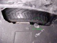
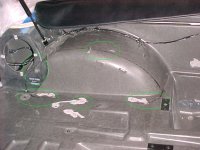
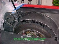
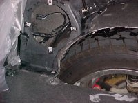
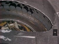
Since they were no longer attached to the original switch the cabling in the car has retreated to somewhere between the body and the 'B' pillar. Access to this area is through a hole covered by a small plate in the rear wheelarch. With this plate removed the cables can be retrieved.
P1370397.JPG
Replacing the steel switch plates poses a problem. The only access to the inside of the body is through the wheelarch hole and then outboard there is a small hole in the 'B' post through which the cabling passes. This hole is too small to pass the plate and the alternatives of either major surgery or complete body removal to fit it are not attractive.

The plate actually only needs material to allow riveting to the body and the 3/8" UNF thread for the switch, so I trim it to retain just these features.
P1370404.JPG

The plate will now pass through the hole - but my hand won't - so some method of holding the plate to the body while being pop riveted is needed.

I cut short length of thread from a 3/8" UNF bolt, drill a 3mm hole through the centre and cut a slot in one end; this I screw through the modified plate and pass a length of cable with a knot in the middle through the hole.
P1370422.JPG

I tape the knotted end of the cable to the three wires, feed the unknotted end through the access and 'B' post holes and out of the switch hole.
P1370408.JPG

I manipulate the plate through the 'B' post hole, pull on the cable to hold the plate firmly against the body and ensuring that the holes in the body and plate line up, fit the pop rivets. The thread length is unscrewed from the plate and the cable pulled through to bring the taped on wiring out through the hole....
A.JPG

The new switch pigtails are soldered and sleeved to the three wires ....
P1370426.JPG
.....which are then pushed back into the body and the switch screwed into place - simples!

As a final check I fit the switch plunger with a small plastic collar and close the door to see if the plunger moves before fitting new rubber pads. It does, but only about a millimetre...
P1370435.JPG
....so I ensure there is enough travel left to accommodated the thickness of the pad and a blob of white paint on the end of the plunger marks the door with the exact position for fitting.
P1370431.JPG

I still don't have my instrument console back in the car (waiting for parts from the States) so I don't yet know if my repair works - still I'm hopeful!

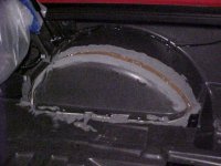
Incidentally, while rummaging around in the cavity behind the wheelarch assess panel I unearthed this
P1370400.JPG
It's a slab of semi-fossilised rubber foam - about the size of your hand. I've no idea if it's meant to be there or if so, what it's meant to achieve. If anyone has any ideas - I'd love to know.
 
Top