Doesn't time fly - my last post on this was in April when I rashly said that it should be down hill (in a positive way) from here on in. It hasn't really turned out that way - who'd have believed it. So what's stopping things? Weather, life (mostly good things - not complaining) and a few things I hadn't expected in finishing off the Corvette which you think will take 5 mins but end up taking 5 days, or thereabouts. Here are a few examples:
The rear number plate light. For some reason the two holes that hold the number plate light on the inside of the rear fibreglass were the wrong distance apart so that the rear number plate light assembly couldn't be fastened properly. (sorry forgot to take the before photo). Thus the glass fibre had to be extended on the left hand side by about 30 mm to allow a new hole to be drilled. I can't quite work this out as this is definitely the lamp that came off the car so theoretically it should have gone straight on.
With the number plate on and the plate light fitted it all looks a bit more secure.
We won't talk about the paint drips .......
View attachment 33388View attachment 33389
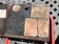
Secondly, the polished stainless steel T-Top pressing. This pressing is held on by a number of screws that fix it firmly to the birdcage. There are two screws that fix in to the upper windscreen surround. On my car this is a new pattern part because the original was unusable. It's probably a bit difficult to gauge from the picture but the lower (plated) bracket sits precisely in the right place to match up with the hole in the pressing. However, having fixed the equivalent plated bracket for the drivers side it was found to be about 8 mm too close to the middle of the car.
View attachment 33390
Thus the rivets had to be drilled out, the bracket removed, the holes welded up, new holes drilled in the right place and then painted. This was done but (I'm going to blame the 32C heat) I actually managed to drill the new holes in exactly the same place as they were before despite have marked out the new location fairly carefully. Doh! or words to that effect. Repeating the exercise a second time gave the (correct) result. You can just see the new holes in the upper half of the picture. This also resulted in a correctly fitting (but as yet unpolished) pressing.
View attachment 33391 View attachment 33392
Just as an aside I have used Rustbuster EM134 epoxy paint to cover the birdcage - a product I really like working with. I think it was recommended to me by someone on this forum - sorry, can't remember who but thanks for the tip. It had a new formulation a while back (with a different mix ratio) and you can see that the revised paint is now much more satin/gloss rather than the original matt.
Between working on these two items I tried valiantly to fit the front bumpers and associated hardware but could not make it work at all with many inconsistencies found. Much frustration, cursing and swearing all round. It took me a depressing amount of time (weeks) to realise that the body was not quite straight on the chassis and needed to be moved over to the drivers side by about 5mm. Thus all connections between body and chassis (mainly the body mounts and radiator support) were removed or loosened allowing the body to be gently rocked into the correct position. I'm not sure if I hadn't aligned it all properly when I replaced the body or it shifted a bit after that because I did not torque down the body mounts until quite recently. I don't know but it seems a lot better now and the front bumper over rider brackets that attach to the bottom of the front crossmember now fit correctly - which is a good sign. One of the problems of doing such an extensive rebuild such as this where just about everything has been undone, repaired and put back together is that getting a good datum point is really quite hard, especially with a glass fibre body with lots of curves. However, I ultimately used the holes drilled in the birdcage sills that align with similar holes in the chassis to make sure that everything was finally in the right place. I'm pretty sure that these holes were placed for this reason and very useful they were too.
Finally (with some good news) I then took the complete rear end apart and sanded down the entire rear end of the body, from door lock panels to the rear valance with a 360 grit paper. I had put a white primer epoxy coating on the body to protect it during the rebuild - it has done its job really well. However there were a number of blemishes to be filled and profiled. This was done - I probably make it sound quick but it took weeks to get everything right - and then a coat of white primer and a very thin white gloss paint were applied to give an idea of how it's all going to look.
With some new Corvette letters and a burglar alarm lock from Eurovettes (thanks Keith!) it all looks quite smart although nothing is fully tightened up yet. The rear lights are my 'test' set - I have a good set for when the paint has been done. The bumpers will need re-plating at some point but that will be for another day. Just an electric aerial and the exhaust embellishers to fit and the rear end is pretty well done. Except final paint of course.
View attachment 33393
Next steps are the front end reassembly and fitting the interior, starting with the three compartments.
 brilliant news ,
  ready for early summer


 and still not right. The rear end is looking good Tim, love a white vette. The interior will really bring things to looking near complete. Great work. Can recommend kim in yate , Bristol for the plating, lots on here use him sbs electro platers I think.