SWPS Centering.

teamzr1

Supporting vendor
Hi Clive F
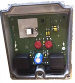
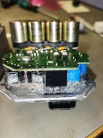
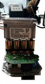
In most cases do not need to get the PCB (circuit board) removed from the case
If having to do that you have to dig out the sealer that is like a glue and then yank PCB off mounts

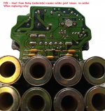
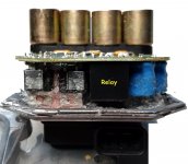
Most times the failure is the relay overheating, bad contacts and gets hot enough to cause the solder joints to break
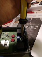
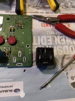
I do is dig the crap out around relay, desolder the legs and pull relay out from the underside of PCB.

New relay I cut the legs shorter and then from underside line legs up through PCB and then solder legs
I also resolder other joints

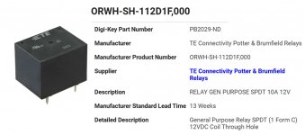
This is more of a pain in ass to do but can be done without taking PCB off and the relay only costs like $2 (USA)
etbcm4.jpg

etbcm3.jpg

etbcm1.jpg
 

clive f

Busy user
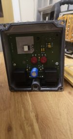
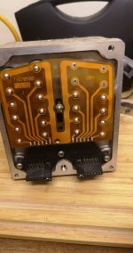
A little confused, mine being a 98, where the circuit board is glued in with resin has the relay on the side you can see, but the reverse side with the pins you describe is the side that I cant get access to as its glued in place all around with resin.82355264_157000025715483_8010298488770265088_n.jpg82643528_467431507533875_6746181835648139264_n.jpg
 

teamzr1

Supporting vendor
97-98 are different than all the others
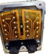
I redid your photos to see better

All the others also have a sealer and what I do is a heat gun (or a hair dryer would do) and heat the sealer up so it softens up and then can cut or scrap off
what is needed to raise the PCB.
May need an L shaped pick to get under to lift upwards after those 2 screws are taken out
98etbcm2.jpg98etbcm.jpg
 

oelarse

Well-known user
97-98 are different than all the others
I redid your photos to see better

All the others also have a sealer and what I do is a heat gun (or a hair dryer would do) and heat the sealer up so it softens up and then can cut or scrap off
what is needed to raise the PCB.
May need an L shaped pick to get under to lift upwards after those 2 screws are taken out
View attachment 12871View attachment 12872
97-00 EBCM's are looks similar and are different then 01-04 .

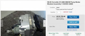
I have a 2000 EBCM ( M without active handling) in my car and it looks 100% like Clive f 1998 EBCM .

I have repaired several later C5 ebcm's and replaced the single white relay on these later C5's which feed powersupply voltage to solonoids and pump .
If you have soldering skills it is possible to replace these relays on early ebcm's ( 97-00) .
These photoes showing when I replaced these relays


IMG_20181216_110157.jpg
IMG_20181216_121217.jpg
 

oelarse

Well-known user
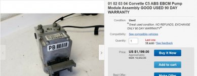
If your 99 have this ebcm which belong to 2001 Corvette I replaced the white relay with the black relay , then someone has modified the ebcm(replaced) on your car with the later model ebcm . I know it has been done by some . IMG_20181203_203127.jpg
As this add from ebay show this is how 01-04 ebcm looks like
01_04 ebcm.jpg
This add show the original (stock) 98-00 looks like ( like my 2000 ebcm):)

98_00 ebcm.jpg
 

teamzr1

Supporting vendor
I bought my 1999 C5 in early 2000 and had only 500 miles on it
I can see why 97-98 would be different as it is installed in the back end and 2000 and newer is by steering rack
up front with less mounting space.
Guess also is if the Corvette has active handling the ETBCMs would be different

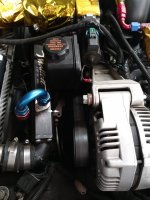
Tried to take a photo of mine, but my heat exchanger to cool engine oil hides the ETBCM

002.jpg

In any case, having spare relays for both design versions is the best path as harder to even find either relay these days
Also needed if working on other types of controllers that also use the same relays
 

clive f

Busy user
After having a break for the car, I checked the tracking set up at home, a tad basic but close enough to know its in a straight line with steering wheen positioned correctly and will have it done properly in a garage shortly.
After a brief test drive this morning the swps is still playing up I think, the codes showing on the dash are all historic but they are, C1277 C 1281 AND C 1288.
to top it all my speedo is now not working, the needle moves as normal on the ignition on sequence and no speed is registered when moving, now I`ve just dropped the back end out of the car recently when replacing the clutch and torque tube bearings, could I have disturbed any wiring that`s plugged into the rear diff area? The ebcm remained in situ at the back so as not to disturb all of the brake lines.
I`m not an electronics person so I think its time to admit defeat and find someone near the isle of wight who can hopefully fix these issues.
 

oelarse

Well-known user
I think you need someone with a proper diagnostic tool to observe the signals from the steering wheel sensor to be able to get some more facts on the table.
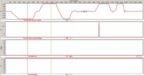
I used my SnapOnEdge scanner and did this recording of these signals when moving my steeringwheel for left to right .
Anlog voltage shall approx. 2.5 volt as seen below when the front wheels are sentered :)
2000 Corvette test av steering wheel sensor vha SnapOn Edge.jpg
 

teamzr1

Supporting vendor
After having a break for the car, I checked the tracking set up at home, a tad basic but close enough to know its in a straight line with steering wheen positioned correctly and will have it done properly in a garage shortly.
After a brief test drive this morning the swps is still playing up I think, the codes showing on the dash are all historic but they are, C1277 C 1281 AND C 1288.
to top it all my speedo is now not working, the needle moves as normal on the ignition on sequence and no speed is registered when moving, now I`ve just dropped the back end out of the car recently when replacing the clutch and torque tube bearings, could I have disturbed any wiring that`s plugged into the rear diff area? The ebcm remained in situ at the back so as not to disturb all of the brake lines.
I`m not an electronics person so I think its time to admit defeat and find someone near the isle of wight who can hopefully fix these issues.

Manual tranny C5, for the speedo the sensor is in the rear end case and outputs the VSS signal which is what the PCM then translates to MPH and sends that data to BCM which sends the data to the I/P controller of dash.
Different for auto tranny Corvette, the VSS sensor is in the tranny

Since you took the whole ass end out, good chance the wiring connector for VSS sensor did not get plugged back in or the wiring for it somehow got pinched or cut
Make sure the ground connections are all good there for ETBCM, etc. and are tight

Let the DTCs that are in history state just age out on their own with more driving to see if they do not come back again
 

clive f

Busy user
just to update the speed sensor was left un plugged after I re installed the back end into the car, DOH!
swps is still the same, so have book in for a visit to Ian Goss next week, hopefully its an easy fix, we shall see, I`m due some good luck.
 

teamzr1

Supporting vendor
Due to the Magna Steer the C5 has, and the ABS system is rather complex in how all this works electronically

Consists of :
1. ETBCM controller
2. Yaw sensor
3. SWPS
4. Speed sensors on each wheel hub
5. ABS system
6. Magna Steer


In short the SWPS is reporting positive or negative turning angle
Each wheel speed sensor reports the speed in MPH for its wheel position
The Yaw sensor is reporting pitch
The PCM is reporting vehicles speed in MPH
The ETBCM is the main controller and commands and reports
If all this does not match then the ETBCM reacts such as pulling out torque, applying brake to one or more wheels
Reports over 80 parameters (PIDs) to OBD-II

  • Common issues with the SWPS, itself is faulty
  • Wiring connector not fully on the sensor or wiring pin crimps faulty
  • Wiring, to one or more wheel speed sensors, or pin crimp issues
  • Yaw sensor or it's wiring
  • Grounds to the ETBCM or the controller itself has issues

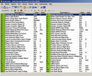
Using a good OBD-II scanner that can connect to the ETBCM. You can monitor those 83 PIDs and see what is not matching

Here is a OBD-II recording of my 1999 C5 as you notice all those PIDs reporting values would quickly point to what is at fault

In simple terms, if the sensors and controller thinks the SWPS reports the car is going straight, but the sensors says the car is dog tracking then controllers react, but it could be a sensor is wrong causing false actions by controller

swps.jpg

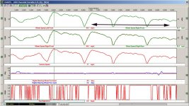
Here as example I superimposed the 2 front wheel speed sensors, and also the 2 rear sensors as is, then to see if they exactly match in reported MPH, along with what the PCM is reporting as C5s speed. They all should match exactly, if not then ETBCM will react
Add looking at the YAW sensor to match up the reported angle of SWPS and Yaw angle
Also, could look at the ABS to see if something then is causing the ETBCM to apply brake to one wheel to straighten the direction of car's forward path

So your OBD-II scanner is your friend and quickly will help pinpoint the problem when doing a testrun with scanner in recording mode to allow then later to replay and analyze what is not working as GM's design.

swp-s1.jpg
 

clive f

Busy user
Thanks, it’s all a bit to technical for me but hopefully it might help the guy who will be trying to fix this for me. I’ve had the car just over 2 yrs and have replaced most things, all 4 wheel hubs and sensors, standard shocks replaced with z06 shocks with the plugs fitted into the wiring to let the computer think that suspension is still standard, can’t remember it’s technical name! And as mentioned earlier ecbm replaced due to abs error codes, so I have no traction control apart from warning lights, I think, as I said electronics aren’t my strong point. I think I’d know if one wheel was braking to try to compensate direction of travel. To be honest I don’t know if any of this stuff really works, car drives and handles great, just seems to be warning lights having a mind of their own😂😂
 

teamzr1

Supporting vendor
Being you had several things changed in the past like the ETBCM, wheel speed and SWPS sensors changed
could easily cause the problems or somewhere in past the steering wheel shaft removed from steering rack
and was not installed exactly right for wheels angle

At the least with the OBD-II scanner can quickly tell if angle of steering wheel is correct to angle of front wheels turned,
if all 4 wheel speed sensors report exactly the same as what speedo MPH on dash shows and the yaw sensor is not
falsely reporting
 

clive f

Busy user
been having a play today with a mechanic friend who has been around to try to help solve this issue, so the question is, the tech 2 when testing the swps shows a signal in degrees for analogue and digital outputs, the analogue output when at zero is spot on with steering wheel and wheels being straight, the digital on the other had is 19 deg off.
where does this digital signal come from, how do I align it with the analogue signal, if I could do that I feel my problem would be solved.DO BOTH OUTPUT SIGNALS COME FROM WITHIN THE SENSOR?
 

teamzr1

Supporting vendor
Not sure but I would think an analog voltage output of SWPS which goes to the ETBCM which then outputs a digital pulse value for the scanner.

Is it possible the steering wheel was taken off in the past and was installed 19 deg off center ?

If you turned SW 19 degrees so the tech-II says zero, how far off are the wheels pointing straight ?

Remember the SWPS might be correct, but it is yaw off or did you check of all 4 wheel sensors report MPH the same ?

If Helps : (C5)

Wiring connector has pins 1, 2, 5 & 6 on the sensor.

Pin 1 is GRY, and it will have a 5 VDC (4.9) reference signal from the EBCM.
It also feeds the YAW rate sensor and the lateral rate sensor.
I would also check for the voltage there. It is also a GRY wire.

Pin 2 is ORN/BLK, and it will have a LOW REF (sensor ground) Signal.
It also goes to the YAW and lateral sensors as the same color wires.

Pin 5 is the Steering wheel position sensor signal phase A. It goes directly to the EBCM Lite green wire
Pin 6 is the Steering wheel position sensor signal phase B. It goes directly to the EBCM Lite Blue wire
If you disconnect the sensor plug, you should read (if I read the procedure correctly) 0.2 VDC on pin 5 & 6

Read the 5 VDC ref voltage to the Low ref pin 2, orange/blk wire should see 5 VDC.
If you measure the low ref pin to ground, it should not read any higher than 5 ohms.

I would hook up a jumper wire to pin #1 on the sensor and when the steering wheel is straight, you should see
The same output on pins 5 & 6. As you turn the wheel all the way right and left,
You should see one pin's voltage smoothly increase while the other one smoothly decreases.

Look at the PIDs I showed in my reply above as what PIDs related to SWPS
 

teamzr1

Supporting vendor
Here you go
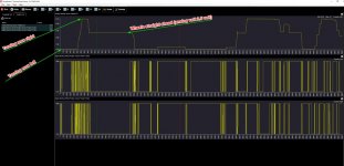
I did a OBD-II scanner recording of my 1999 C5 at idle for you
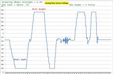
SWPS works from 0 to 5 volts (analog)

When steering wheel is dead straight the sensor reads 2.5 V
When turning steering well full locked left then SWPS measures about zero volts

When back to center (2.5V) and going full lock right then SWPS outputs 5 V

So in this recording, starts at far left of my chart
Steering wheel dead straight and SWPS outputted 2.5 volt
Close to zero volt then you know I went full left and when SWPS outputted 5 volts then you know I turned steering wheel full right

You can then cross my results with your scanner data doing the same tests I did and see if voltages match
If matches then sensor is not at fault (unless your data shows random voltage or dead spikes)

So could steering wheel have been put on when steering rack was not dead center or
could front alignment be off ?

I attached the raw scanner data of my tests, and you can import into Excel spreadsheet and do what you want and also make charts of data

Note the small voltage up down I did on purpose short left/right to see voltage then go up/down

BTW - what SWPS is all about - power steering as ETBCM sees wheels being turned it applies controlling power steering fluid flow
SO when turning steering wheel PS fluid flow pressure is changed, so it makes it easier to turn wheels (rather old days when no PS you had to have big balls to be able to full turn)

These early SWPS was so much a problem that GM came out with a PS valve fluid bypass so that if SWPS did fail the power steering would still work but the amount of pressure turning the steering wheel requires the same amount of steering effort by driver


SWPSangle.jpg
 

Attachments

  • 99rebelswps.TXT
    909.6 KB · Views: 1
Last edited:

clive f

Busy user
Thanks Teamzr1, my mechanic friend did as you said and the voltage went to zero on one lock, about 2.45 straight and 5 v opposite lock, voltage movement on graph was smooth, no spikes indicating bad readings. So the sensor is working, I removed the rack to change the harmonic balancer and fitted the swps by removing the column in the car at the same time, and marked up the column joint before taking apart and being careful about reassembly.
If the column connected to the intermediate column or the rack via a splined fitting I could understand it being easy to be a few degrees out, but as we are talking about square bar connections then smallest amount it could be out is 90 degrees surely which is a huge margin?
wheel alignment has been checked twice now .
if I turn the steering wheel to zero deg on the digital output the tyres are turning to the right by 3” when looking at the outer edge of the tyre comparing to when it was straight which is zer deg on analogue reading, worth noting volts in this position is reading 2.6v
 

teamzr1

Supporting vendor
DTC C1288 you mention in 1st post
defined and another of my posts that you need to look and see if the yaw sensor is at fault
rather than the SWPS

What is C1288 code meaning?

The Vehicle Stability Enhancement System (VSES) is activated by the Electronic Brake Control Module (EBCM) calculating the desired yaw rate and comparing it to the actual yaw rate input.
The desired yaw rate is calculated from measured steering wheel position, vehicle speed, and lateral acceleration.

The difference between the desired yaw rate and actual yaw rate is the yaw rate error, which is a measurement of oversteer or understeer. If the yaw rate error becomes too large, the EBCM will attempt to correct the vehicle's yaw motion by applying differential braking to the left or right front wheel.

The amount of differential braking applied to the left or right front wheel is based on both the yaw rate error and side slip rate error.
The side-slip rate error is a function of the lateral acceleration minus the product of the yaw rate and vehicle speed.
The yaw rate error and side-slip rate error are combined to produce the total delta velocity error.
When the delta velocity error becomes too large and the VSES system activates, the drivers steering inputs combined with the differential braking will attempt to bring the delta velocity error toward zero.

The VSES activations generally occur during aggressive driving, in the turns or bumpy roads, without much use of the accelerator pedal. When braking during VSES activation, the brake pedal will feel different from the ABS pedal pulsation.
The brake pedal pulsates at a higher frequency during VSES activation.

You may have to do a testrun with a scanner and record what YAW sensor is outputting and see if that is the cause
maybe clear that C1288 DTC first
Then do a testrun recording yaw and see if you can make that DTC trip and then see what yaw values are

Keep in mind this could be a flaky issue with the ETBCM itself as to cracked welds or the internal relay, or it's wiring or ground

I would see if the ETBCM is commanding any of the 4 wheels brakes, even a little bit as to ABS and not a SWPS issue

From my idle testrun there are 3 yaw PIDs

yaw.jpg
 
Last edited:

clive f

Busy user
Thanks again, braking whilst driving I`m pretty sure I`d notice a pull to one side through the steering wheel, plus I have check wheel temperatures and they are all the same so I don`t think this is making my brakes come on at all, I will try to check this yaw sensor out though, its booked in with a corvette garage tomorrow who can hopefully sort the issue and have a much better understanding of it than me lol.to me it still comes back to the swps, its secondhand, it seems to be working, but why is the analogue angle different to the digital angle? if its down to something on the four wheels why didnt it show on the old sensor before it died? everything worked fine then the old sensor stopped working, it was stuck in 270 deg on test, new replacement sensor now I get two different readings on the test and cant understand why, its either new variables come into play, or the sensor is no good? It would be great to have another to just compare, its such a shame you`re so far away Teamzr1 or I`d be round your place lol.
 
Top