New to this - C3 THE PLOT THICKENS

Alex Gray

CCCUK Member
Right, it’s getting a little more confusing.

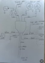
The red wire that was dislodged from the fuse box was indeed the ignition hot, I’ve reinstated this and proven 12v at the relay control module when ignition on. Ran her up to temperature and with fingers crossed awaited the fans…. They didn’t run!!!

So I wondered if it was the signal from the stat and to try and prove this I jumpered them to chassis ground with ignition hot, nothing!!!!

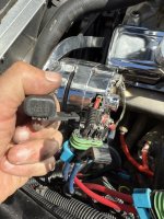
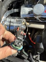
I started having a look on the power circuit side and have found two inline modules that on closer inspection have burnt out. See the picture attached.

What’s confusing me is “why would these burn out as a result of there being no ignition hot”? As before that was knocked out everything ran like a dream???

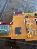
My next question is, am I allowed to use these halford bits to replace the inline fuses? They are rated to 30A but I’m not sure if they are suitable for engine bay use??
 

Attachments

  • IMG_8224.jpeg
    IMG_8224.jpeg
    247.2 KB · Views: 14
  • IMG_8223.jpeg
    IMG_8223.jpeg
    248.5 KB · Views: 15
  • IMG_8225.jpeg
    IMG_8225.jpeg
    200.9 KB · Views: 15

teamzr1

Supporting vendor
Was this screwed up when you first bought this C3 ?
If so, sounds like last owner had this problem and was trying to debug it
Inline modules ?
Are those fuse holders, or what their purpose ?

How does this controller know what the coolant temp is ?
Is the wiring like 14 or 12 AWG gage ?
 

Alex Gray

CCCUK Member
Hi. Sorry, I appreciate I’m not explaining it clearly so I’ve done a drawing. Hopefully that makes it clearer.

So I reinstated the ignition hot as that had come loose. But further diagnostics found the two fuse blocks (I think that’s what they are) between the alternator and relay box had melted out!
 

Attachments

  • IMG_8228.jpeg
    IMG_8228.jpeg
    112.2 KB · Views: 9

teamzr1

Supporting vendor
Did you look closely and try and find any label or name on controller or fans as who makes these
to then search on internet for instructions of installing ?

You sure both circuits go directly to the alternator ?
As I asked what gauge are the wires for that, look like 14 or 12 AWG ?
I would think 20 Amp would be fine but could be they are using

20 AMP per relay and fan
Your drawing too dark so I redid it

Could test and use a jumper between the 2 wires of one melted connector and see how that controller reacts

8228.jpg
 

Alex Gray

CCCUK Member
Thanks, yes no manufacturer label on the controller I’m afraid.

The power circuits are roughly 6mm (so I think roughly 10awg.

The control circuits look like 0.5mm so 20awg.

I’ll jumper the melted blocks tomorrow and see how we go.

👍🏼
 

teamzr1

Supporting vendor
OK More info
I think that wiring was too close to engine/exhaust and cause of melting, so move them away

Look at the cooling fans, there should be a amp draw label on them and reason you say wires are like #10 AWG
that would support 30 AMPs per fan
I see others also went to the Alt instead of the car's fuse panel could not handle all that AMP draw

Jumper, 1 or both fuse pair wires and test

I have to think there would be a single pole switch by driver to override the controller
like if racing would not want the fans on and enough natural flow would be fine
 
Last edited:

Forrest Gump

CCCUK regional rep
Is that melted part a fuse? Surely fuses normally just blow the wire inside them, not melt to ash like that.
The case part isn’t damaged so the heat must be electrical rather than from proximity to headers.
Halfords electrical parts are fine, although I would use fully insulated female spade connectors instead of those ones in your photo that don’t have insulation on the spade.
Have you established if the fans actually run or not, independent of the control module?
 
Last edited:

Alex Gray

CCCUK Member
Yes. The melted parts were fuse holders.

I’ve replaced them and put in two new 30A fuses. According to the wiring diagram it seems that each fan has its own 30A supply into the relay control module.

So. With the ignition hot reinstated and the new fuses in place I ran her up to temperature and hey presto, the fans came on.

Took her out for a run and about 30mins in I was at some traffic lights when I heard the fans cut out (temp way above start set point).

Took her back and one of the fuses had popped.

Further diagnosis has found that with both fuses in place, both fans come on. If I take one fuse out and engage the opposing fuse blows instantly. This happens both ways!?!

It’s as if both fans have a mysterious parallel feed so that if one fuse pops, both fans draw current from the remaining fuse holder.

From my wiring diagram the only way I can see this happening is via the control module.
 

Forrest Gump

CCCUK regional rep
Yes, I would now suspect there’s a fault inside that module, there was obviously something going on to cause the fuses to obliterate first time round.
I had a Kenlowe control module a bit like yours at one point….until it went wrong. I‘ve done away with it and just wired in a relay with a single stage temperature switch in the radiator top hose.
 

Forrest Gump

CCCUK regional rep
IMG_1708.jpeg

You would need two relays or you might find a high current relay that could cope with both your fans ( I’ve just got one fan)
Edit…..sorry you’re an electrician so sure you know all that!!
 

teamzr1

Supporting vendor
I assume the center relay is controlling each fan's relays ( left and right one)
and whatever is wrong is causing voltage feedback so that both fans are being drawn on only one of the 30 amp circuits

Are the relays in a socket or are they soldered directly into that daughter board ?
Look on the back side of that and see is any solder issue to one of the relay lugs ?
Also see if any labeling of maker on back sides

If you can check/test each diode and transistors
From back side, test first the center relay for contacts being stuck of fused closed state
Or take relays out and test it one as to their coils and normally open or closed contacts
Look and see if the relays are rated for at least 30 Amps
If common relay types replace
Would be nice to know what the 8 dip switches on/off combo is commanding to that I/C chip

IMG_8220.jpg
 
Last edited:

teamzr1

Supporting vendor
If those relays are common, 5 lug open/closed contacts should be easy to find new ones
Should be easy to use multi meter and see if relay coils active in the state of contacts switch or are stuck

Or remove that controller and do this with 3 new relays and be better long term with 2 30 AMP breakers

duelfans.jpg
 
Top