72 Corvette - Restoration Updates

Mad4slalom

CCCUK Member
There didn't seem to be much point in posting a whole series of pictures about refurbishing the wiring - it would have been very repetitive - but I am pleased to report that all 5 looms (instrument, engine, forward lights, rear body loom, power windows) are all now done, getting them all completed on an I've started so I will finish basis. A bit tedious but worthwhile in the long run.

The instrument loom is partially in place waiting for the steering column to be installed..... and trialling some LED replacements. Here's a green one for the indicator lamps on the speedo but fitted (somewhat confusingly) in the main beam on idiot light socket, just to see if they fit properly - which they do.
View attachment 21199 View attachment 21202
The rear body loom was a bit of a mess when it came out - most of the binding tape was missing and there was a little damage - but this has now been repaired and trial fitted. It seems to go in quite nicely so far. I have added an extra wire for an electric aerial but otherwise it is as GM intended.

View attachment 21201View attachment 21198
The other looms are waiting to be installed...
View attachment 21200

I have started painting the steering column which I would like to fit as part of the instrument wiring installation. I am doing one section at a time which although taking longer is actually easier as it's a bit fiddly painting these parts, particularly the lower two sections where one slides over the other. The original as delivered finish can be seen on the third section at the lower right - pretty rough - but it is coming up quite nicely. The paint colour is Mini Chilli Red which is as close as I can get to the original GM colour and seems to be a good match to the other red parts in the interior. It has the advantage of being easily available from Halfords.
View attachment 21203

Numerous small parts are being fitted - too many to list really, but here are the upper windscreen surround fitments as an example. I think these will need to be drilled later. so that the stainless steel trim cover can be fixed down.
View attachment 21197

In preparation for the front clip replacement the bonding surfaces have been cross hatched with a Dremel.

View attachment 21196

Next week I should be able to fit the steering column and the front clip. It should start looking a bit more like a Corvette again. Fingers crossed.
Meticulous attention to detail as usual Tim. Cant wait to see the finished car ! 👍
 

TimP

CCCUK Member
Had a reasonably productive week this week and tackled two jobs that I have been putting off for as long as possible.

The first job related to the dash top which I didn't think would need for a long time yet as I had forgotten that the dash gauge cluster fixes on to the dash top rather than the other way around. ie the dash top provides the rigidity and structure that allows the dash gauge to be hung from it. It wasn't until I tried to trial fit the dash cluster that I realised that there was nothing to fix it too yet. Thus I dug it out from where it had been hiding and had a close look at what I had - which was quite frankly, useless. The vinyl is very brittle and breaks off very easily. It is cracked and one of the speaker grilles that is formed into the vinyl has almost disintegrated. It is unusable but could potentially be recovered - but I still need it for the dash gauges - so I decided to strip it down to just the basic skeleton.

Taking it from .......
Interior-22.jpg Interior-23.jpg
....to ...
Interior-24.jpg Interior-25.jpg
It does have a significant advantage for me in that now being stripped you can see much more of what is going on around it. When putting things, particularly the wiring loom, back together this makes life a whole lot easier. I will have to recover or replace it in the future but for now it will remain stripped.

The steering column paint work was finished so it is now ready to go back into the car...

Engine Bay 17.jpg

But most importantly I have resolved the issue with the gear lever hole in the floor. I needed to reduce the size from an auto sized hole to a manual sized hole. The previous owner had made an aluminium plate to cover the gap but although functional it was a bit of a bodge.
So taking this (below) as the start point I removed the interior and exterior auto sized reinforcements (there is one under the floor too).....
Interior-26.jpg
... and fitted a manual reinforcement plate (from the old manual boot) underneath the car and placed a bit of strong card between it and the glass fibre floor. I then feathered the edge of the hole that needed to be built up and braced it all with a clamp that I carefully (ahem) made in the card.
Interior-27.jpg

...and then added 6 layers of glass fibre matting.

Interior-28.jpg

Then did the same trick along the other axis of the hole....
Interior-30.jpg


To be continued.....
 

Attachments

  • Interior-29.jpg
    Interior-29.jpg
    132.1 KB · Views: 2

TimP

CCCUK Member
.... continued from before....
Sanding this down, trimming the hole to the right size and removing the lower brace gave me a strong structure on which to mount the reinforcements.
Interior-31.jpg
With the old reinforcement to show the change in size...
Interior-32.jpg
With the new manual reinforcement...
Interior-34.jpg
With the lower reinforcement.... You will notice that all the old holes have been filled ready for the new ones I in the right position
.Interior-35.jpg

With the new boot.....
Interior-36.jpg

Which, having now completed this task, I can fit the sound deadener...
Interior-37.jpg
I won't be drilling the new holes and fitting the gear lever boot permanently until I have the gearbox back but it is all ready for this and I can install further sound proofing and the wiring and vacuum looms before that needs to happen (I think).
 

Attachments

  • Interior-33.jpg
    Interior-33.jpg
    162.1 KB · Views: 0

TimP

CCCUK Member
This week's focus has been on getting the wiring looms and related hardware fitted on the interior.

First problem to solve was how to fix relays and braces to the new and refurbished birdcage structure. On the new parts, holes were pre-drilled in the right places ready for a self tapping screw. Never been a big fan of these to be honest and I couldn't find the right size of screw for the holes that were there so decided to use rivnuts instead which work very nicely. Shown here with the centre dash pad support..... They give just that little bit more confidence that they aren't going to come loose again later on.
Interior-38.jpg Interior-39.jpg Interior-40.jpg

I wanted to fit the dash gauges. I had made 4 replacement brackets for the hinge posts a year or more ago whilst doing the birdcage. Fitting them was quite straight forward although I might have to swap out the rivets at some time for a weld or something low profile on the outer side - I think the rivets may foul the door seals. Time will tell.
Interior-41.jpg
..... thus allowing the driver's gauge cluster to be trial fitted.
Interior-42.jpg

Thought I would do the same on the passenger side but realised that this panel needed a bit of work - the ventilation mechanism was very rusty and seized up. It was stripped, de-rusted, painted and refitted using bolts rather than rivets as originally. The plastics have become quite brittle over the years - something that has given me a lot of problems with the drivers gauge cluster - and I didn't think the main moulding was going to survive the fitting of a couple of pop rivets as they require a fair bit of pressure to fit. Nutlock nuts also allow just the right amount of freedom in the joints to give a nice smooth movement without any slop. The cosmetics of both these panels will have to wait for another day but I did want to get everything working for the first trial.
Interior-44.jpg Interior-45.jpg Interior-46.jpg

Having painted the steering column a while back it was then fitted with a new rag joint and seals at the front end. The electrical connections were all burnished to give good contact. Hopefully this shouldn't have to come out again (famous last words) and the connectors on top of the column were all hooked up.Interior-47.jpg

Next, I will be working on fitting the drivers gauge cluster and centre console gauges and then testing and debugging all the electrical issues that I have probably created during the rebuild. I'm going to leave the vacuum side of things for a while until I know the electrical bits are working properly. The speedo cable needs to be rebuilt but fortunately the rev counter cable seems to have escaped the ravages of time and will just need a clean. Hope to be able to connect a battery and show some signs of life in the next instalment - fingers crossed.
 

Attachments

  • Engine Bay 18.jpg
    Engine Bay 18.jpg
    169.2 KB · Views: 6

Chuffer

CCCUK regional rep
This week's focus has been on getting the wiring looms and related hardware fitted on the interior.

First problem to solve was how to fix relays and braces to the new and refurbished birdcage structure. On the new parts, holes were pre-drilled in the right places ready for a self tapping screw. Never been a big fan of these to be honest and I couldn't find the right size of screw for the holes that were there so decided to use rivnuts instead which work very nicely. Shown here with the centre dash pad support..... They give just that little bit more confidence that they aren't going to come loose again later on.
View attachment 21417 View attachment 21418 View attachment 21419

I wanted to fit the dash gauges. I had made 4 replacement brackets for the hinge posts a year or more ago whilst doing the birdcage. Fitting them was quite straight forward although I might have to swap out the rivets at some time for a weld or something low profile on the outer side - I think the rivets may foul the door seals. Time will tell.
View attachment 21420
..... thus allowing the driver's gauge cluster to be trial fitted.
View attachment 21421

Thought I would do the same on the passenger side but realised that this panel needed a bit of work - the ventilation mechanism was very rusty and seized up. It was stripped, de-rusted, painted and refitted using bolts rather than rivets as originally. The plastics have become quite brittle over the years - something that has given me a lot of problems with the drivers gauge cluster - and I didn't think the main moulding was going to survive the fitting of a couple of pop rivets as they require a fair bit of pressure to fit. Nutlock nuts also allow just the right amount of freedom in the joints to give a nice smooth movement without any slop. The cosmetics of both these panels will have to wait for another day but I did want to get everything working for the first trial.
View attachment 21423 View attachment 21424 View attachment 21425

Having painted the steering column a while back it was then fitted with a new rag joint and seals at the front end. The electrical connections were all burnished to give good contact. Hopefully this shouldn't have to come out again (famous last words) and the connectors on top of the column were all hooked up.View attachment 21426

Next, I will be working on fitting the drivers gauge cluster and centre console gauges and then testing and debugging all the electrical issues that I have probably created during the rebuild. I'm going to leave the vacuum side of things for a while until I know the electrical bits are working properly. The speedo cable needs to be rebuilt but fortunately the rev counter cable seems to have escaped the ravages of time and will just need a clean. Hope to be able to connect a battery and show some signs of life in the next instalment - fingers crossed.
An impressive amount of work you have on the go . (y)
 

fine69

Busy user
These last two weeks have been a little slow, mainly due to the cold weather, but I have managed to rebuild the Z shaft that is part of the clutch mechanism.
Here is the shaft after cleanup with the new parts to be fitted. The grease that normally sits in it was completely solid and I doubt was providing any lubrication at all.
View attachment 20898

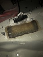
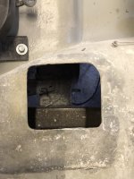
Quite a satisfying job to do and it fitted straight in. The engineering is perhaps a little crude but it works really nicely and the action is very smooth without any play. I'll take simple and effective any day. Fitted it looks like this - although the felt seal and the little plastic cap to keep the grease in the shaft are missing at the moment - more items for the snag list. The chassis bracket needs some TLC but once the weather warms up a bit ....
View attachment 20899

The distributor has been sitting in a box for the last three years but even so it was a little rusty and very dirty.
View attachment 20900 View attachment 20901
Stripped and with a few new parts it was much improved. The original points and condenser looked new so were kept. BHCC, who sold me the car, said at the time that they had tried (and failed) to start the engine and I think they must have fitted these as part of that effort. The vacuum advance was tested with a vacuum pump and it failed due to a slight leak. The mechanical advance was cleaned, lubricated and refitted. Afterwards it looked like this..
View attachment 20902
The outside of the distributor shaft was painted with a high temperature paint and then everything was reassembled with the points set to a default gap....
View attachment 20903

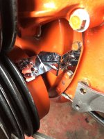
All the hinges were fitted ready for the front clip to be reinstalled - doors will be necessary for alignment and fit.

View attachment 20904
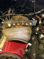
However, most of the time has been taken cleaning the instrument loom contacts. There are probably 60 or 70 contacts that need to be stripped, cleaned, greased and reassembled. Most are of the type that are pushed out by bending a small tang on the top of the contact. I used a modified screwdriver for this...
View attachment 20906 View attachment 20905

I used a WD40 contact cleaner as the solvent and a medium grade wet-n-dry paper to clean up the copper. Both together they worked very well. A dielectric grease was applied to try and stop any further corrosion. The tang then needs to be bent out again to catch inside the plastic moulding on refitting. I've got another 5 or 6 contacts to do in the main fuse box next week and then this loom is ready to be refitted. Most of the relays have been tested and amazingly are ok - the only item that doesn't seem to work is the ignition switch buzzer, which will need to be replaced. I have already replaced the radio part of the loom with a set of ISO connectors to make it easy to upgrade the radio. The Corvette (Pioneer made) radio has an eardrum busting 3.2watts per channel at 5%THD. I'm probably not going to be using it much but even so it's going to sound pretty poor compared to a modern set up so it might have to go. I'm assuming that it actually works of course - which is unlikely - but the ISO connectors will make replacement really easy.
Next weeks job is to finish this loom and fit it. Then do the same thing to the engine loom. I also want to hang the doors and trial fit the front clip. The weather is dry for another week so this looks achievable. The bonding adhesive will need a temperature of at least 15C so my plan for getting the front clip fully installed by the end of January was probably a tad optimistic and will have to wait until it gets warmer.
I love the c3 Z-bar arrangement, easy to adjust, super smooth action. yes it looks crude but functions very well. Mine's a pro touring vette, gets plenty of abuse, handbrake turns, power slide etc. I just adjust the clutch every now and then (takes 10 minutes) and away i go. A way nicer feel than the hydraulic setup on my Dad's '69 Camaro. In fact we took off the hydraulic setup and went back to the z-bar.
 

TimP

CCCUK Member
I fitted the dash cluster and applied some power through an old Weir power supply that I bought at a boot fair a few years ago for £3. It's been powering my electrolysis tank up until now but with this I can control the power supplied, see what is going on in the looms with the meter and limit it to a couple of amps when a short occurs, which has happened a couple of times already. Saves frying things if using a real battery.
Wiring 15.jpg

With the negative to the bird cage and the positive lead to the horn relay 'busbar' (if the front lights loom is connected) or directly to the back of the fuse box (if not) I can supply power to the various looms gradually in a reasonably controlled way.

All switched on but nothing happened! .... and with the gauges installed it's very difficult to diagnose what's going wrong.

I removed the cluster and made a small plate with 6x 16mm holes and an earth point. Also the headlamp switch was removed and plugged into the appropriate socket. With this set up used instead...... the indicators worked ... yea!
Wiring 17.jpg

And then the same with the night lamps for the speedo, rev counter and centre gauges...
Wiring 18.jpg Wiring 19.jpg Wiring 20.jpg

... that last one included the parking break light which just needed earthing (as its not currently connected) to get the correct (2 wire) warning light on. Not shown is the drivers side courtesy light that also came on when I earthed the headlamp switch casing. Some of the lamps look dimmer than others but I think that's an illusion created by camera angle - they all looked ok in the car.

I have rebuilt the connections on the back of the gauge cluster - I'm pretty sure the earths weren't earthed and hopefully that should sort it out. The headlight main beam warning bulb does not come on when I hit the floor switch but I think might be because the lighting circuits are not connected at the moment. I willl get back to that later....

I think (perhaps someone can confirm) that rotating the headlight switch knob dims or brightens the dash lights. With LED's now they are either on or off but I think that should be ok.

I have watched many videos showing how to get the dash cluster back in a c3. All seem to recommend a different approach and some have been quite brutal. Seems best with the dash pad off and the steering column lowered a little but there's not a lot of room in there. 50 year old plastics are fairly brittle and there are a few sharp edges to watch out for but it does ease in with a lot of guidance.

Lastly, I really would like to have a few words with whoever thought it was a good idea to put the fuse box hidden away where the steering column goes through the firewall. I already have cracked my head on the steering column once trying to see what's going on down there and I know it's not going to be the last time either. Probably should have kept my cap on rather than using it to protect the paint on the steering column......
 

Attachments

  • Wiring 16.jpg
    Wiring 16.jpg
    162.9 KB · Views: 3

TimP

CCCUK Member
I think I mentioned before that 50+ year old brittle plastics were a bit problematic. The last fitting of the dash gauges resulted in an ominous cracking noise - something I had become all too familiar with. The result was a decision to step back a bit and do some repairs and rework the dash light wiring.

The ominous noise turned out to be the turquoise/green binnacle pod - it had actually broken in three places. And this was with me being careful!

One of the mounting lugs had broken off - so repaired it by embedding a rivnut in a remade lug. Not a big fan of self tapping screws in plastic - the threads seem to strip or crumble when the plastic becomes brittle - and this approach is a little bit more positive in its location. The bottom fixing lug had also broken off so that had to be redone with fibreglass. Neither are particularly pretty fixes but they seem to be effective and hopefully stronger than before.
Interior-49.jpg Interior-48.jpg

Another problem I was having with the dash is the limited room to fit it amongst the wiring loom, steering column, hood release etc. Apart from cracking the plastic parts I was also having trouble with bulbs falling in to the gauges, the light sockets pulling out of the back of the gauges and generally not being confident that the connections were good once the dash was in place. Thus I decided to p-clip the wiring loom to the bird cage and rewire the back of the gauges so that all the dash light wires came out from the back and round to the top of the gauges where a couple of waterproof connectors join the new lamp wiring to the loom. The earthing was improved by running cabling between the major metal parts and removing corrosion and paint (where paint shouldn't have been applied - guilty your honour) and similarly using connectors to join to the loom. It's a trial set up to see if this idea was an improvement using cabling that I already had, but it works well and I can now fit (or remove) the dash in a minute or so (with the steering column lowered by about half an inch) and be comfortable that everything is still hooked up correctly. When the re-trim is done the dash will have to come out again and at that point I will use the correct coloured wires etc. to make the job look a bit tidier and professional. The third repair cab be seen at the 10 o'clock position on the speedo binnacle (right hand in the picture)

Interior-51.jpg Interior-50.jpg

Just in case anybody is interested in what the new LED dash gauge lights look like... here they are in red, a little uneven (not sure why - could be my camera work) but I will try and resolve this next time the dash comes out. Having all eight gauge lights on results in about a 120 milliamp current flow - with the original bulbs it was about 2.5 Amps, so quite a reduction.
Interior-52.jpg

Having worked on the electrics now for a few months I decided to have a break and do some bodywork .... so the hinge posts went on ...

Body Reinf 16.jpg

.... the front clip was rescued from the garden and, with the kind help of a neighbour, refitted....
Body Reinf 17.jpg Body Reinf 18.jpg Body Reinf 19.jpg

It fits quite nicely but there is a little fettling to do (particularly on the passenger side) before being bonded in place - which hopefully I will do this week. Pleased to have the car looking like a Corvette again. :)
 

Oneball

CCCUK Member
Looking like a car again. Amazing what you can do when you put some effort in.

I used some tile clamps to help hood mine in place and ensure alignment with the doors. E8D5757C-1421-4872-B776-16E750F0DABA.jpeg
 

TimP

CCCUK Member
Looking good Tim. Are you planning to paint the car yourself, or is that going to be outsourced?
Thanks and good question!

I will definitely do all the bodywork myself. Although I have done a lot of repairs already there are one or two places I missed which will take a couple of days to sort out. I might be in the minority but I really like working with glass fibre - to my mind it is very satisfying.

Once all the repairs are done and all the mouldings are in place I will do as much of the body prep as I can leaving it with a coat of epoxy primer (current thought) for a while. Hopefully at the same time the car will be approaching the point where it can be taken safely on the road. Prior to a final (and probably expensive) professional paint job I will run the car for 6 months or so and make sure that the body doesn't crack or craze. Unfortunately I can find many roads in the area which are potholed enough (welcome to Sussex!) to give this a good test. To make the car presentable I will probably put a wrap on it which could be quite fun to do in the interim. Still a few months away from that point but that's my approach for now.
 

TimP

CCCUK Member
Looking like a car again. Amazing what you can do when you put some effort in.

I used some tile clamps to help hood mine in place and ensure alignment with the doors. View attachment 21619
Aha - that's interesting. Was wondering how to do this. I have put the hinges on in readiness for door alignment but wasn't quite sure how to get a nice consistent transition between the panels - so thanks for this, it's a really helpful tip.

Before bonding I also need to redo the front clip support bar (just behind the headlight cut outs) and align the hood. I think it's going to be quite tricky bearing in mind how much surgery this car has had but could be quite fun too. More likely a complete headache but let's stay positive for the time being .....:)
 

TimP

CCCUK Member
Spent a week or so aligning and fettling the front clip/hood/doors/firewall/chassis extensions etc. combination - which is coming together quite nicely - allowing me to be fairly confident in starting to fix things in place more permanently. Starting with bonding and riveting the front reinforcement bar.....
Body Reinf 20.jpg

... and the headlamp pod support/reinforcement bar...
Body Reinf 21.jpg
Both were painted with an epoxy topcoat that hopefully will keep them rust free for as long as possible. The original items had disintegrated completely from corrosion when the car arrived so a little time spent protecting them should help with longevity.

Being somewhat uncoordinated, using adhesive/sealant is a messy business and it went just about everywhere - seemed to end up wearing most of it. I'll try and remove the clamps in a few days when I'll find out how many of them I have inadvertently bonded to the reinforcement bar.
 

Mad4slalom

CCCUK Member
Spent a week or so aligning and fettling the front clip/hood/doors/firewall/chassis extensions etc. combination - which is coming together quite nicely - allowing me to be fairly confident in starting to fix things in place more permanently. Starting with bonding and riveting the front reinforcement bar.....
View attachment 21659

... and the headlamp pod support/reinforcement bar...
View attachment 21660
Both were painted with an epoxy topcoat that hopefully will keep them rust free for as long as possible. The original items had disintegrated completely from corrosion when the car arrived so a little time spent protecting them should help with longevity.

Being somewhat uncoordinated, using adhesive/sealant is a messy business and it went just about everywhere - seemed to end up wearing most of it. I'll try and remove the clamps in a few days when I'll find out how many of them I have inadvertently bonded to the reinforcement bar.
Epic work Tim, as always, full of admiration for your approach and tenacity. I still have a bumper here , just have’nt been near eastbourne lately.
Catch up sometime if I am up or you are down in sunny cornwall. 👍
 

TimP

CCCUK Member
Thanks! Sorry to be slow responding to your post - have just spent the last few days in hospital having my right knee replaced. Everything has gone very well but I think it will be a good few weeks before I start working on the car again and it will be a long time after that before the front bumper becomes a critical item. - so don’t worry at all about that.

it would be great to catch up sometime and compare notes! Look forward to it and I’ll definitely let you know if I’m planning a trip to Cornwall.
 

mickn

CCCUK Member
Thanks! Sorry to be slow responding to your post - have just spent the last few days in hospital having my right knee replaced. Everything has gone very well but I think it will be a good few weeks before I start working on the car again and it will be a long time after that before the front bumper becomes a critical item. - so don’t worry at all about that.

it would be great to catch up sometime and compare notes! Look forward to it and I’ll definitely let you know if I’m planning a trip to Cornwall.
Having followed this thread from the start I have been greatly impressed by your ability to tackle any task rebuilding the car so I'm a bit surprised that you couldn't replace your knee yourself, surely that would be a doddle compared to the restoration of a basket case C3? ;)
 
Top