72 Corvette - Restoration Updates

TimP

CCCUK Member
With the temperature approaching a heady 3 degrees I have ventured to the workshop once more to finish the driver's seat......

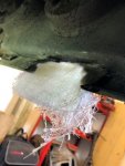
As predicted the seat back support bolt that had sheared in the seat base was a nightmare to remove and despite my best efforts I had to resort to a drip and tap to resolve the problem.

A steel reinforcing plate was made up with holes drilled out in the appropriate places and riveted in place to check for alignment. You can also see one of the two small reinforcing plates for the seat back pivots.
Seat base 21.JPG

Then the base was rejoined with the back to make sure that the strengthening pieces fitted were still allowing everything to work properly. I've used (mainly) new hardware as the old ones were in pretty poor shape.
Seat base 22.JPG Seat base 23.JPG

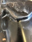
All seemed to work ok and so the plate was welded on and the entire base painted
Seat base 24.JPG

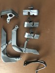
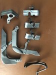
I had purchased an excellent set of tracks from a fellow club member but I had not realised that the '72 and later tracks are about 30mm longer than the 69-71 equivalents. One of my old non-serviceable tracks was cut and a section added to the 'new' ones. It's surprising how many quite significant design changes there are between model years. I wonder what prompted GM to g to the trouble of redesigning the floor pan and seat mount arrangements.
Seat tracks 2.JPG

This now gives a set of tracks with the correct lengths for my car.
Seat tracks 1.JPG

The 'arrow' mounts were then switched around - they face the other way around on later tracks - and fixed back on. I have left the original rivet hole on both tracks (only one had the 2 spot welds filled when the photo was taken) so that the process could be reversed easily if required.

So that just leaves.... a little bit more painting to be done, the reinforcement plates to be rivetted back in to the car and then everything reassembled and tested. With some warmer weather on the way I can probably get that done next week. A lot of work for a driver's seat but hopefully it should be good for another 49 years and I've learned a few things along the way. ;)
 

TimP

CCCUK Member
One more post on this seat: With the warmer weather I managed to get three coats of paint on the reinforcement plates underneath the car and once dry, carefully rivetted them in place.

First the seat belt reel reinforcement plate. (seen here from underneath)
Seat base 27.JPG

The front seat mounting bolts reinforcement plate (well most of it anyway):
Seat base 28.JPG

and the rear seat mounting reinforcement plate next to the transmission tunnel...
Seat base 29.JPG

I'm not sure what is supposed to be in place to reinforce the other side as whatever was there on my car has long gone. Does anyone have a picture of what is supposed to be there on a '72 model?

Lastly, I have temporarily put the old seat base wires back in place and test fitted the seat base back in the car.
Seat base 25.JPG

You can see the big head rivets holding the reinforcement plates in place. I have also made some mounting spacers(?) made out of rubber/cork gasket material that go between the fibreglass and the seat track bases. Although probably not necessary I think they should help spread the load a bit and provide a bit of isolation between the floor and the seat base. Just some cleanup, paint and reassembly to do now for this area to be complete.

Next on the list is probably refurbishment of the the u-shaped reinforcement bracket that goes inside the transmission tunnel. It is seriously rotten and unavailable new as far as I can see, so it might be a challenge. I'm hoping that the car will go off to CK for birdcage work soon and that will leave space in my garage to do something a bit different.
 

TimP

CCCUK Member
Yes - indeed. Perfect!

This looks like the same plate as the one near the transmission tunnel. That's great - I can make a couple of these using the other ones as a pattern.

Many thanks for taking the trouble to take and send the picture - that's been really useful.
 

Oneball

CCCUK Member
Yes - indeed. Perfect!

This looks like the same plate as the one near the transmission tunnel. That's great - I can make a couple of these using the other ones as a pattern.

Many thanks for taking the trouble to take and send the picture - that's been really useful.

No problem, annoyingly because Iā€™d cut the floors out of mine for the race seats I had all those bits until a month ago when I chucked them in a skip:oops:
 

Mad4slalom

CCCUK Member
One more post on this seat: With the warmer weather I managed to get three coats of paint on the reinforcement plates underneath the car and once dry, carefully rivetted them in place.

First the seat belt reel reinforcement plate. (seen here from underneath)
View attachment 9462

The front seat mounting bolts reinforcement plate (well most of it anyway):
View attachment 9463

and the rear seat mounting reinforcement plate next to the transmission tunnel...
View attachment 9464

I'm not sure what is supposed to be in place to reinforce the other side as whatever was there on my car has long gone. Does anyone have a picture of what is supposed to be there on a '72 model?

Lastly, I have temporarily put the old seat base wires back in place and test fitted the seat base back in the car.
View attachment 9461

You can see the big head rivets holding the reinforcement plates in place. I have also made some mounting spacers(?) made out of rubber/cork gasket material that go between the fibreglass and the seat track bases. Although probably not necessary I think they should help spread the load a bit and provide a bit of isolation between the floor and the seat base. Just some cleanup, paint and reassembly to do now for this area to be complete.

Next on the list is probably refurbishment of the the u-shaped reinforcement bracket that goes inside the transmission tunnel. It is seriously rotten and unavailable new as far as I can see, so it might be a challenge. I'm hoping that the car will go off to CK for birdcage work soon and that will leave space in my garage to do something a bit different.
Wow! Serious resto going on there Tim. šŸ‘
 

TimP

CCCUK Member
A bit of a hodgepodge of updates this week.....
In the last post I learned about the rear seat mount reinforcement plate for the bolt next to the sill. The ones on my car had both rotten away but with Oneball's photo (many thanks!) I realise it's the same as the centre mount so using that as a basis I have been able to make 2 more.
Seat base 30.JPG

I was able to borrow a boroscope/endoscope/whatever from a neighbour and was able to check the condition of the cylinders by having a peek inside the spark plug holes. All good news - no cylinders with water or rust and everything looked remarkably clean so that was good to find. :)
engine clean 1.JPG

I decided to refit the crossmember to get it temporarily out of the way so I treated and painted the lower parts of the chassis rails and bolted it back on - it went on really easily. I think it looks quite smart - very pleasing as it had taken about a week to clean, de-rust and paint inside and out. A good comparison to the prop shaft which was how it used to look.
Cross Member 1.JPG

And now for something completely different.... This is one of the two worst parts of the bodywork remaining (see pic). It's on the rear where the exhaust panel fits - in fact one of the bolts for this panel goes into the reinforced hole on the right. This reinforcement plate was drilled out and cleaned up.
Exhaust panel 1.JPG

The damaged area was the trimmed back so that there was something solid to fix onto and a backing was made of cardboard, covered with cling film to act as a release agent, and clamped in place
Exhaust panel 2.JPG

The fibreglass (4 layers) was added using the backing as a former, I also need to make sure that it was sticking well to the perimeter of the hole.
Exhaust panel 3.JPG

The cardboard former was then removed. The new fibreglass was then covered with more fibreglass at the back (another 4 layers) with about 2 inches of overlap with the existing glassfibre (forgot to take a pic of that). Then more fibreglass (2 layers) at the front also overlapping with the existing glassfibre, and afterwards trimmed to match the lower line of the original moulding. When fully cured it was ground to approx. the right contour and the lower edge was shaped where it meets the top edge of the exhaust panel to make it nice and straight

Exhaust panel 5.JPG

That concluded the 'structural' part of the repair to give it strength and rigidity. It was then given the right cosmetic shape with some filler. It's not finished yet but it's heading in the right direction and I think you can see what I am aiming for. Hopefully once complete it should not look like (from the outside) it has been repaired - only the rear repair work will show. I believe it is strong enough - it is thicker than the original glassfibre and has bonded well with the original bodywork - and the whole panel feels more solid already. Once it looks right and fits well against the exhaust panel I will drill the holes back out and refit the reinforcement plate. I also need to work out where the big hole in the middle of the repaired area goes. I will post some pictures of that next week.
Exhaust panel 6.JPG

That leaves just one other significant body repair required - more about that later.
 

Attachments

  • Exhaust panel 4.JPG
    Exhaust panel 4.JPG
    42.3 KB · Views: 7
  • Seat belt cover 1.JPG
    Seat belt cover 1.JPG
    60.9 KB · Views: 6

TimP

CCCUK Member
Very kind of you to offer but I have the rear right bumper and all brackets so I should be able to work it out. Perhaps more importantly, I need to sort out this first.

Pax corner 1.JPG

Which is as ugly in the metal (so to speak) as it looks in the picture. I'm pretty sure the body isn't supposed to have a rear spring inspection point. I repaired the rear bumper front mounting point last year so that's all ready to go. At least this is the last damaged area of body like this.
 

TimP

CCCUK Member
More importantly than the outside, what does it look like from the inside?
Do you mean how does the hole look from the inside? If that's the case then it looks Ok - not brilliant but I believe it is fixable although I will have to be careful on a number of points including making sure that the repair is not too thick as this will effect the fit of the bumper mounting brackets - a problem I had fixing the front. I haven't been able to do anything today but I will post a photo tomorrow.
 

Corvette

Well-known user
Hi Tim, by the inside I meant original bonding stripes present and NO under seal on inside of bodywork covering bodged repairs. Around that rear panel hopefully from inside the one inch wide bonding stripes are present?
 

TimP

CCCUK Member
Hi Frank,
Got it - many thanks for your help. I know there isn't any previous repair here or underseal/pug etc. I don't think anybody has tried to sort this out before. I'll post a picture tomorrow but I think that there is a missing or broken bonding strip which goes along the join where the blue arrows are in the picture - at the moment the panels above and below this line can be moved relative to one another so there is definitely something wrong here. On the driver side you can see the end of this strip in the gap to the left of the left hand arrow. I haven't had time to investigate fully but I will start that tomorrow. The driver's side is in relatively good condition so it's a useful comparison.

Exhaust panel 7.jpg
 

TimP

CCCUK Member
I wasn't able to spend much time on the car today but I did take a couple of pics behind the rear glassfibre panels to show the damage from this side.

In this picture you can see a little bit more detail on the damaged passenger side . As far as I can see (and with my limited knowledge) a 3-4" length of the bonding strip has broken off at the red arrow - it should extend along the join to the right. I do have the S-shaped glassfibre joining strip (not quite sure what to call it)that goes along the edge marked by the blue arrows (which oddly looks like it is being held up by an axle stand, but it isn't) and that will be bonded back again in due course. The small bit of glass fibre reinforced filler by the green arrow was left by me when repairing the hole to the left and will be removed as part of the repair as it will probably interfere with the inside bumper mounting bolts.
Body pax rear qtr 2.jpg

In comparison here is the 'good' driver's side.
Body drv rear qtr 1.JPG
 

TimP

CCCUK Member
Yes to both - but it is the spur on the left hand end of part 29 (passenger side)in your diagram above which has the last 3-4" missing. All the rest of it is still in place in the car.
 

TimP

CCCUK Member
A little more time spent on the glassfibre fix this weekend and I also refitted the reinforcement plate for the exhaust panel. The original hole ...
Exhaust panel 1a.JPG

now looks like
Exhaust panel 9.JPG
I put a coat of primer on it to highlight any areas still requiring attention (there are a couple) but that will be sanded off again when the body is prepared later in the rebuild. It's close to where I want it to be now in this area but I will finish this after the corner repair area is done and the holes are drilled for the bumper bracket.

And on the seat front ...... I've fitted new zig zag springs. Just some foam now and this seat can be recovered, reassembled and put to one side.
Seat base 33.JPG
 

TimP

CCCUK Member
Another quiet week but I did manage to do some cleaning and painting. First.. another seat related pic of the tracks.
Seat tracks 3.JPG

..... which are now fitted in the car with a new seat adjuster spring. With a repaired base and with the old seat cushion installed I sit about an inch or so closer to the roof. When I fit new seat foam I will probably sit another inch higher still - just as well it's a T-Top. These are the last seat pictures for a while. Promise.
Seat base 34.JPG

I have started cleaning the engine and these items came off first with the driver side exhaust manifold.
Heat Shields 2.JPG

These cleaning/painting tasks keep things moving whilst I plan out separating the body from the chassis. More of that in the next couple of updates. Have a good week everybody.
 

Attachments

  • Heat Shields 1.JPG
    Heat Shields 1.JPG
    173.1 KB · Views: 3
  • Heat Shields 1.JPG
    Heat Shields 1.JPG
    37.5 KB · Views: 2
Top